This structure is a bit outside Payette Valley Models’ usual selection criteria; it is not directly railroad-related, it is late in the era generally modelled, and it is not only “back east”, but Canadian as well. But still, it’s an interesting building that is suitable for many layouts.
The prototype was built in 1910 near the shores of Georgian Bay in Ontario, Canada. It was the residence of a family working a 50-acre farm, having two barns, chicken coop, and a windmill-driven pump with cistern for water. The buildings no longer exist and the land is now part of a neighborhood.
Two photos of the prototype exist: the first from the 1940s, the second from the 1960s.
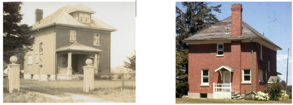
from such evidence models are created
Side Note: For those interested in detailing the interior
The prototype had a 3rd-floor full open attic – a garret. On the second floor, four bedrooms in each corner with a small bath center rear. There was an octagonal shaped common area in the middle.
The main floor was split in half along the depth: a parlour in the front right, a dining room in the rear right. Entry “room” on the left front with stairway along the left wall and opening to parlour through the long wall. The stairway had a landing hallway up with a window, then turned into the interior to the second floor. The stairway to the attic from the second floor crossed over the landing of the lower stairs along the left wall.
An open hallway ran between the front and rear doors with a half-bath against the middle left wall and kitchen in the left rear. The outside side door opened to a landing with stairs down to a full cellar and a short flight of stairs up to the first floor next to the half-bath. A cistern was located under the kitchen in the left rear corner of the cellar and fed by a drain pipe from the gutters on the rear wall.
Interior details are not included with the kit.

As always with building a kit, read through the instructions before beginning assembly.
Construction – Background
This kit is made entirely of 3D-printed semi-transparent “smoky black” resin. This material may be lightly machined and will (usually) survive mild abuse. While not as brittle as many 3D resins, it is not “break-proof”. Small parts can easily break.
The material may be fastened with “superglue”, epoxies, or “Gorilla Glue” (a polyurethane substance originally intended for woodworking); regular plastic glue will not hold and wood glue will not form a sufficient bond. Gorilla Glue is suggested as it doesn’t require mixing and allows more time to apply clamps and adjust placement if necessary. It also cures clear. It generally sets enough for mild handling in 2 hours.
There may be nubs on the resin pieces. These should be removed by light sanding. Fingernail or jewelers files also work well.
Glazing material in the form of uncut acetate is included but roofing material is not. Roof material and color are dependent on the desired age of the structure and whims of the modeller. Cedar shake shingles were originally used, the roof was re-done with dark green asphalt shingles sometime in the 1940s; a brighter green shingle was applied in the 1970s.
There are four major pieces: the foundation, the main walls as one piece, the roof trim, and the roof itself. The roof has a dormer printed as one piece. The front porch comes in pieces and can be tricky to assemble; the rear porch is a single piece.
It is strongly suggested the parts be painted before assembly. The cellar windows are embedded into the foundation; the prototype cellar window frames are metal and painted a dark green. The foundation and window sills are concrete. It may be desirable to paint the interior walls flat black … depending on window treatment and whether the interior is detailed or lit. Window shades on the prototype were dark green.
One method of painting brick: Paint the bricks pumpkin orange. When that paint has fully set, apply a thinned coat of red oxide or similar color. This wash does not need to be evenly applied; several thin washes are suggested until the desired effect is obtained. Slight color variations between washes adds a subtle multi-colored effect. The prototype color is shown in the photos but yellowish or grey brick was not uncommon in the region. Don’t forget to do the chimney at the same time as the walls – a uniform “unevenness” in color is desired.
Construction – Assembly
Step 1: Walls – Foundation
The foundation has cross-bracing built in which makes handling the assembly during construction easier. Sand as necessary to make sure the foundation sits flat and that the windows and door opening are on the upper side.
Fasten the walls to the foundation. The corners should line up as should the door opening on the left side and chimney slot in rear. There is bracing for support across the door opening on the foundation – remove this after the glue has set.
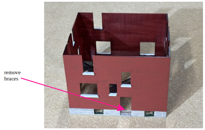
The window sills are concrete – maybe something special in 1910
Step 2: Windows and Doors
The windows ares et in from the outer side of the wall; they should be mounted flush to the interior side of the walls. The windows should be fastened from the interior.
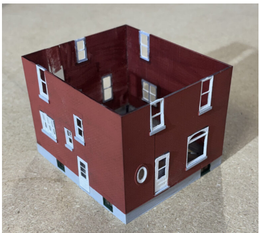
Any glazing and window treatment (such as blinds, curtains, coloring, etc) should be done now. Since the windows are intended to fit flush to the inner wall, one possible method of glazing is to simply glue a strip of acetate across the windows against the wall rather cut individual pieces for each window. Cutting individual pieces is recommended if the model is to be a foreground structure.
Zapf’s Canopy 560 Glue works well to hold the acetate material to the wall. Although white when applied, the glue dries clear. Don’t forget glazing on cellar windows (embedded in the foundation) and dormer.
There are two styles of main front window included: a square top and a rounded top. The rounded section of the main front window was stained glass. Tamiya has a set of transparent color acrylics suitable for coloring acetate. At some point in time, the rounded top window was replaced with a clear square top window. Many of the other windows have alternates included in the kit: open, partially open, closed.
There is no way to properly identify which window goes where. The two lower right side windows are identical (and do not have options). The two upper side windows and front right window are identical and have options. The remainder simply “fit” in the intended openings. The photos are guides to widow placement.
The oval window and upper section of the main front window could be colored with transparent paint such as that offered by Tamiya. It may be desirable to place some form of black material inside the window glazing to prevent viewing on the unfinished interior.
Once the windows and doors are painted, they might need mild sanding on edges – the paint may make the difference between fitting easily or not. Fingernail files work well. Want fairly tight fit; not loose enough for gaps, not tight enough to require force to place.
Doors are in two pieces: inner and outer. In later days, the prototype doors – inner and outer – were all white with old brass colored doorknobs. The earlier photo indicates a darker front door
Step 3: Roof
The roof trim piece and the roof should be treated as a sub-assembly. Because of potential irregularities in the surfaces, the two pieces should be heavily clamped until the glue is set. Clothespins work well. Gaps will show on the final model. Use enough clamps that the gaps no longer show. The draft kit used Gorilla Glue with no problems; a 2-part epoxy such as that provided by Loctite will provide a stronger bond but is messier to deal with. Roughen the mating surfaces lightly before gluing. Moisten the surface if using gorilla glue.
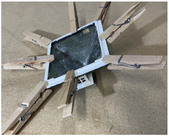
Make sure all interior work is complete: window treatments, paint, etc. Although the bottom remains open, the cross-bracing may hinder access once the roof is placed.
Fasten the roof sub-assembly to the walls. There are tabs to assure proper placement. Make sure the dormer is to the front. It may be advantageous to use “bean-bag lead-shot” style weights while the glue sets to assure a good tight fit with no gaps.
Make sure the blank face of lower half of the chimney is flat – sanding may be required. Make sure brick face faces outward. Fasten lower section of chimney to rear wall. The top of this section should just extend into roof support trim.
Step 4: Porches
Assembling the front porch may be the most difficult part of this kit. Getting the porch columns properly positioned and vertical is the most challenging part of this kit.
There is a base piece, two columns, a roof trim piece, and the roof itself.
The front porch is to be fastened to the front wall but it needs to be lined up such that the left side of the porch roof lines up with the left front wall edge. There is a thin marker line on the front wall of the foundation; the left edge of the porch base should just cover that line.
When placed, the left edge of the porch roof should line up with the left wall.
The porch pillars will hold the front of the roof; the pillars overlap the framing of the roof support and the roof peak is just below the upper left window sill. When everything is in place, finally fasten the porch to the front wall. When that has set, place the roof.
It may prove helpful to assemble the front porch with the model front facing up.
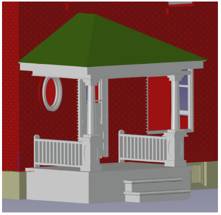
[Here’s what I did. It may or may not work for others:
– Fasten the roof to the roof trim piece. Set aside.
– With the model sitting on its foundation, line up and fasten the porch bottom in place.
– Sand or file the porch column bases flat.
– With just a smidgen of glue applied to the column base, set the column in place. The post might stand vertical on its own … or apply braces to hold the post in position until the glue sets. A full cure is not desired.
– When the glue has partially set – enough to hold the column in position with no brace – set the model so that the front faces up.
– Place a bit of glue to the top of the columns, then place the roof assy on the front wall below the 2nd-floor window so that it just touches the columns.
– Lean a weight against the roof to force firm contact with the columns. The columns should have enough play to position them properly against the roof support piece
The rear porch is a single piece. It tucks up to the chimney while sitting flush to the wall and base. Fasten with the glue of choice. Let sit until glue sets.
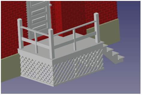
The roofs over the side and rear doors are optional; they are a later addition to the structure (compare the 1940s and 1960s photos). If added, place the porch roof supports on either side of the doors such that the upper side of the supports are two brick heights above the door.
When set, place the roofs.
Note: the side door roof tucks in tight against the side bathroom window sill.
Step 5a: Final Pieces – Chimney
Place the upper section of the chimney. It should line up with the lower section.
Step 5b: Final Pieces – Roofing or Gutters?
Modeller’s choice: Roofing first or gutters?
The gutters may be placed now but they are fragile and subject to crushing if handled. They happen to be a place suitable for holding the model …
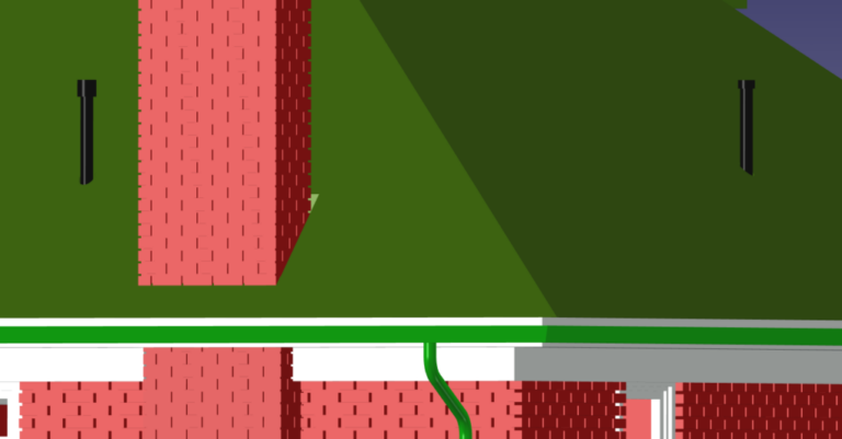
An extra gutter section is included for patching if necessary. The alternative is to place the roofing material first, noting that the two vent pipes need to be placed.
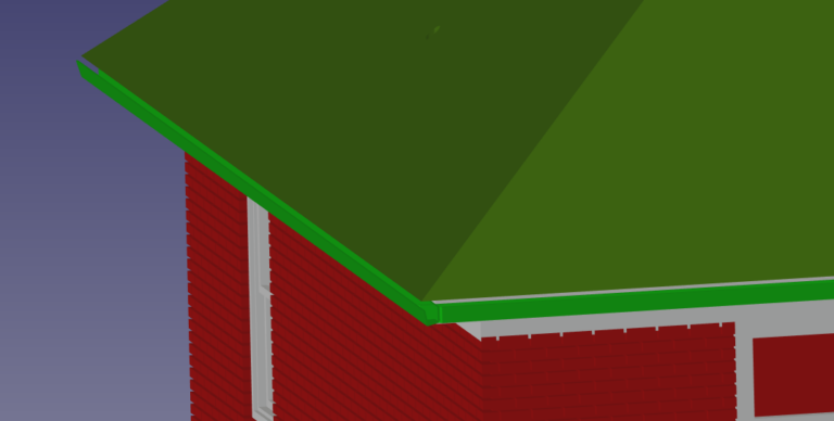
The gutters are fragile. One edge is slanted, the flat side goes against the roof trim piece. The front porch gutter is one piece. Place it against the porch roof trim as shown.
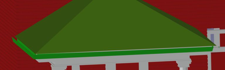
There are four sections of gutter for the main roof: two longer than the other two. The two longer gutters go along the right and left sides; the shorter lengths go along front and rear.
Place along the roof trim making sure the corners line up.
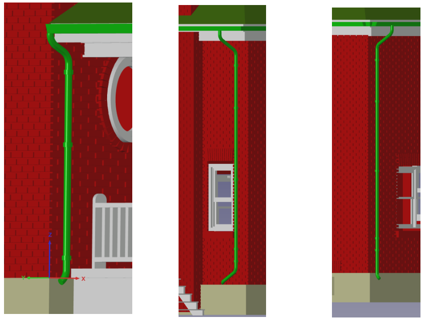
Fasten the three drain spouts:
If not done so already, place the two vents into the roof
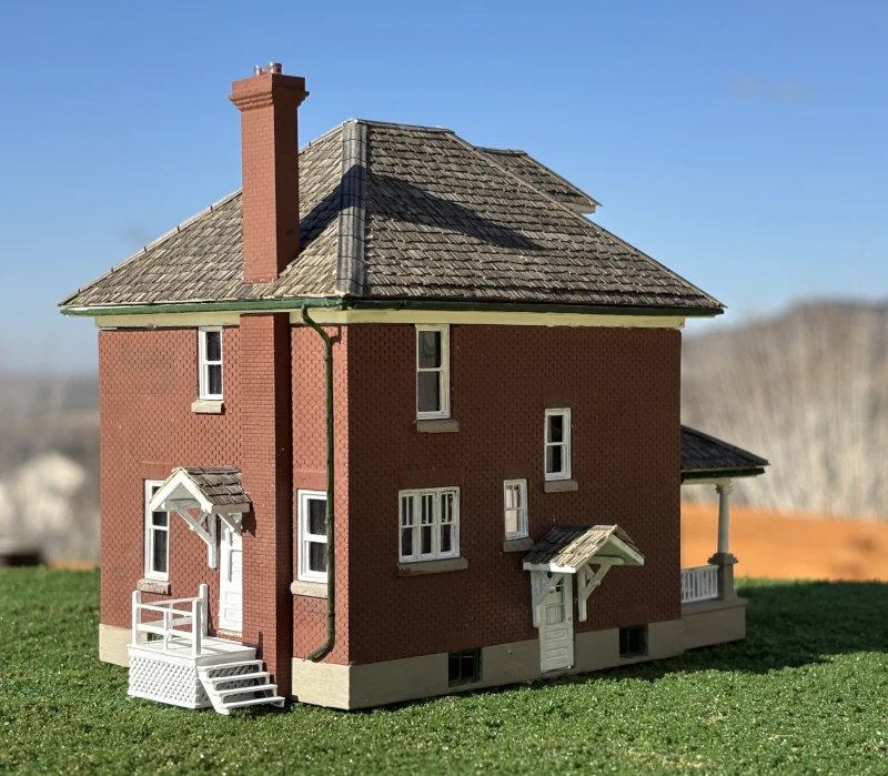
If not added before, apply roofing material. Wild West Scale Models offers a nice selection of shake shingles as do other suppliers.
(the pre-production model shown below uses Wild West #508)
Finale
Place completed model in desired location.
Any questions? Contact us at info@PayetteValleyModels.com