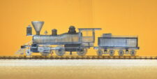
HOn3 2-6-0 “Mogul” Locomotive “Glenbrook”
This model is intended for background display – an engine sitting inside a roundhouse, an engine on a siding or deadline, a source of engine parts laying around. It is not a fully accurate model of the Glenbrook.
This kit is offered as a generic background model roughly based on the 1875 Baldwin 3’ narrow gauge engine now known as the “Glenbrook”. This engine spent most of its life operating on several of the logging lines around Lake Tahoe.
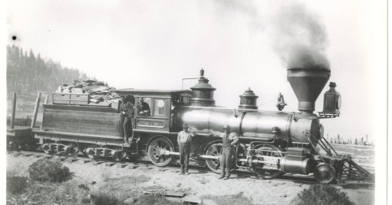
I first came across this engine years ago when it was stuffed and mounted next to the old Carson City Mint (now the Nevada State Museum)
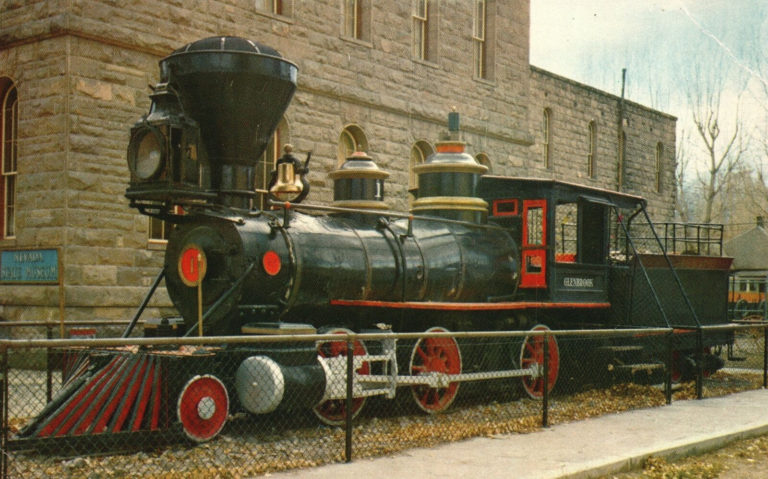
The engine has since been restored to operating condition and now lives at the Nevada State Railroad Museum outside Carson City.

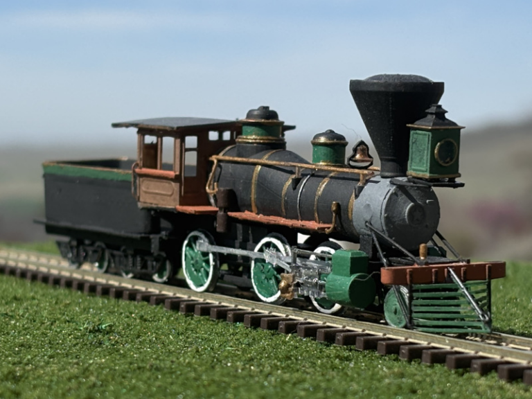
One of PVM’s pre-production units:
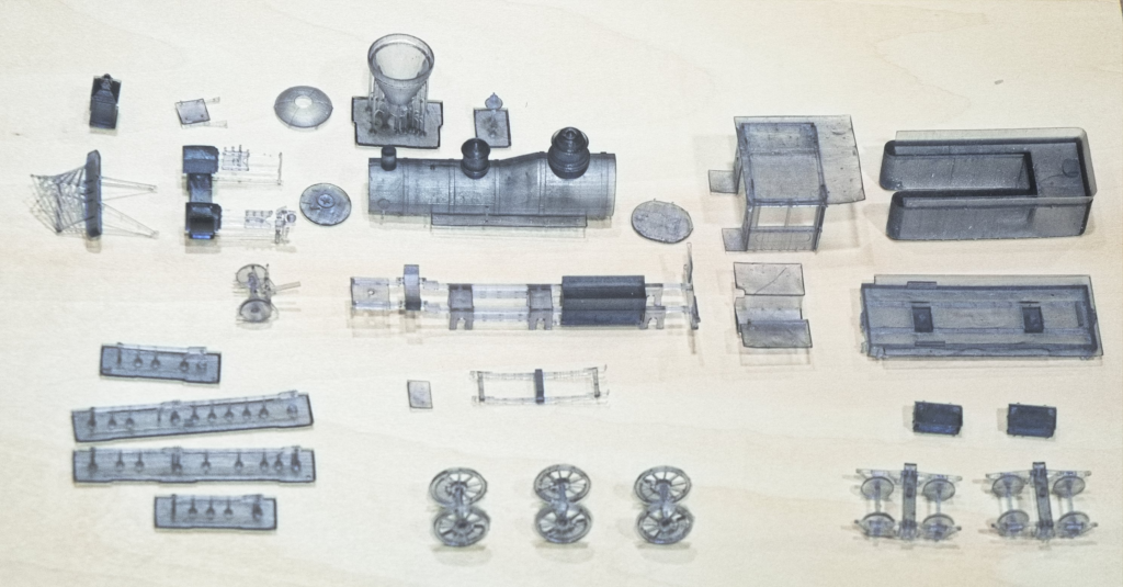
OK – let’s get started. Here are the parts for the Mogul engine:
THE MATERIAL
The parts are 3D-printed with a resin that accepts sanding and drilling. While the size of HO parts can require delicate handling, the base material is fairly rugged. The cured material is a transparent smoky gray. I recommend that a primer coat of thinned paint be applied; this material seems to suck up the first coat.
This style of engine when new was highly decorated and probably had a gloss-finish paint job with polished wood and brass. Schemes were colorful and individual – an engine crew was assigned a specific engine and kept up the appearance. Mostly black engines didn’t come along until later … late 1880s/90s – which would also be appropriate for this engine in its later life – a worn-out working engine.
This resin is not a typical plastic and regular plastic glue does not work (including MEK). Superglue works – but sets fast and sometimes “tweaking” of parts is necessary. Epoxy also works well but is such a pain to work with … but necessary where strength is needed. Gorilla Glue seems to offer a suitable compromise between ease of use and setting time. It requires a bit of moisture to act as a catalyst and dries clear.
While it’s usually best to paint parts before assembly, it may prove better to defer painting the boiler until after Step 3: Boiler Assembly
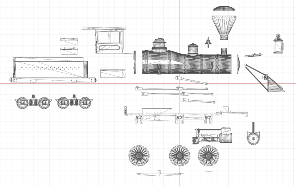
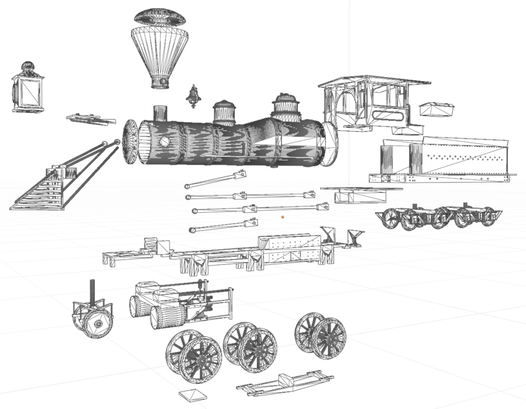
Exploded Views:
Step 1: Cab Sub-Assembly
CAUTION: The grab rails on the cab sides are very delicate
Paint the cab pieces as desired before assembly. This is a wooden cab, not steel.
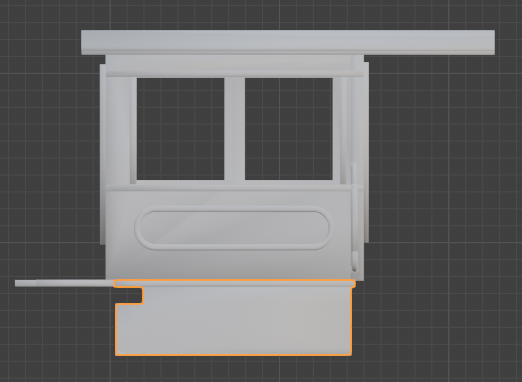
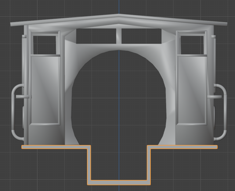
Fasten the cab floor to the cab body. Note the notches face forward. They provide clearance for the boiler.
Place glue along the bottom edge of the cab; it sits on the floor
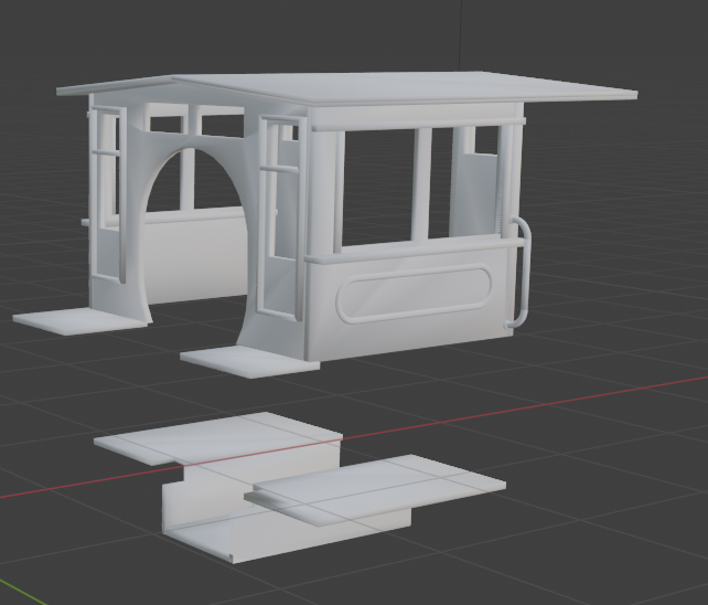
The cab sits on top of the floor piece with the notched corners to the front, flush against and level with the front tabs on the cab.
The platforms should tuck up on the left side as shown. The tabs to the sides of the floor fit onto, not into, the bottom edge of the cab.
These views of the cab assembly shows the floor piece outlined in ORG.
2) Frame and Drive Wheel Assembly
CAUTION: The tabs on the upper frame – especially the cab support tabs – can easily snap off
Pieces needed for this step:
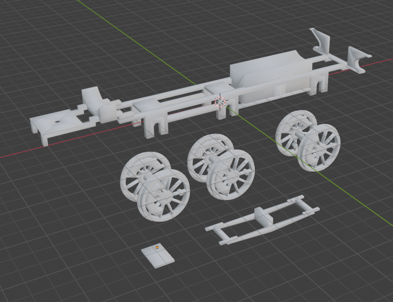
Make sure any remaining manufacturing nubs on the axles are sanded or filed smooth. They need to freely rotate until the rods are in place.
The frame pieces should be painted flat black; the inner sides of the wheels, flat black, rust, or dirty steel. The rims are steel, while the spokes and side rims a “decorative” color. It was not uncommon for the outer side of the rims to be painted white; any developing cracks would show easier.
Turn the upper frame upside down. Place the rear two pair of driving wheels in place. Although these wheels will be fixed in place, they need to rotate freely until the drive rods are placed.
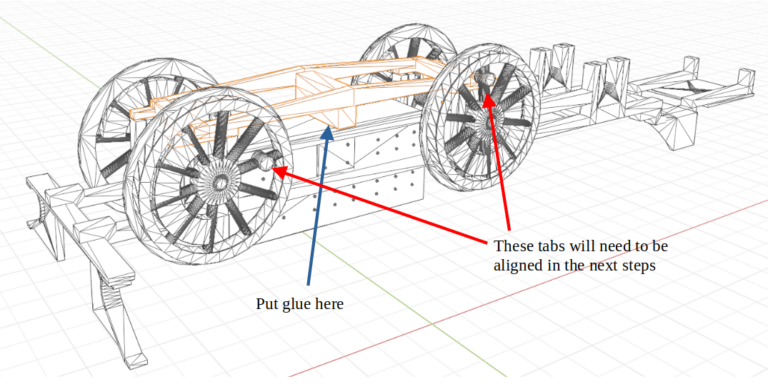
Fasten the lower frame in place. Glue should only be applied to the center block to give the best results. Make sure the tabs of the lower frame overlap the notches in the upper frame; they can be glued down after the wheels and drive rods are placed..
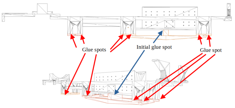
After the drive wheels and frame are in place, glue may be carefully placed on the retaining tabs such that the wheels can still rotate (until the drive rods are placed). Next, the same process with the third wheel set. Place the axle into the notch and fasten the frame plate to the upper frame notches. Be careful not to glue the wheels. A touch of glue on the tabs should do it.
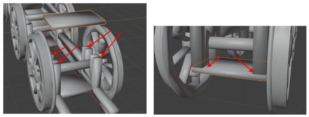
Step 3: Boiler Assembly
This part is simple enough – simply fasten the smokebox front and firebox face to the boiler. Make sure the detailed firebox face is facing out from the backside of and vertical to the boiler.
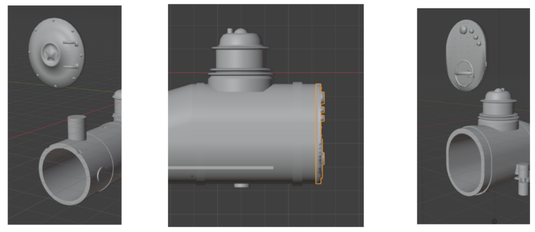
The smokebox front is aligned with the boiler front such that the “hinges” on the smokebox door are horizontal to the right when looking into the front.
When the glue has set, sand or file and overlapping lips; the front and rear faces should form a smooth junction with the boiler. Now would be a good time to paint the boiler assembly. The bands may be brass, the dial faces white, the front star red, and the domes a “decorative” color with brass bands.
Step 4: Main Assembly
Here’s where it begins to look like a steam engine under assembly rather than a bunch of parts. It’s not difficult but all three sub-assemblies need to be tweaked at the same time to assure a good 3-way fit.
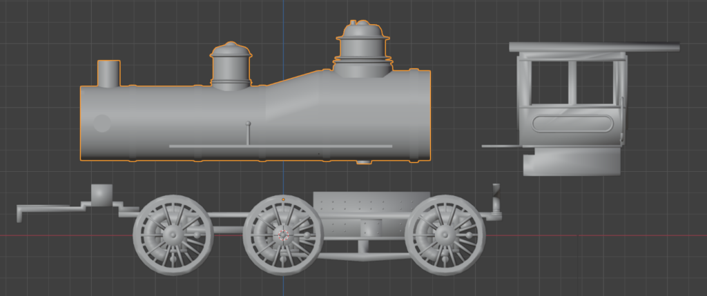
First the boiler fits a short distance into the cab.
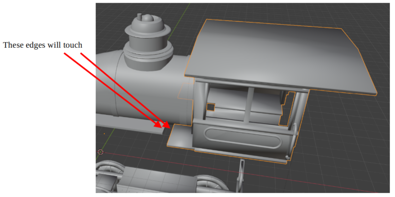
The left-side running boards will line up
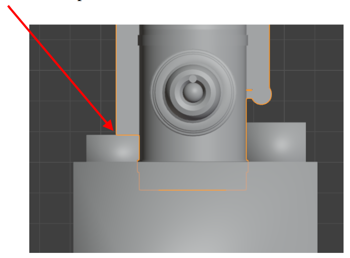
The cab sits on the frame with the cab floor butting up against the firebox on the frame assembly
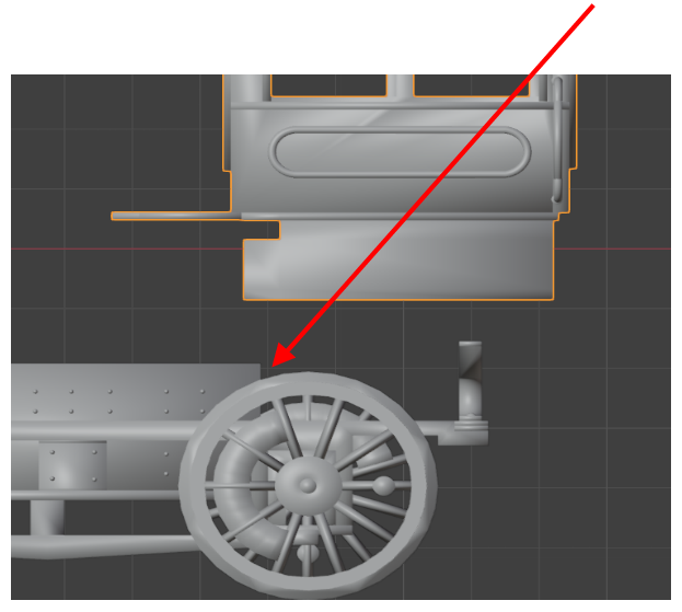
The rear tabs on the frame for cab support will touch the bottom of the cab floor. They are a bit fragile but not so much that more than normal care is needed.
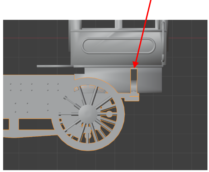
The assembly at this point should look like this
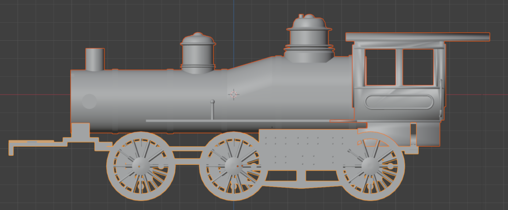
Step 5a: Main Rod Assembly
This may be the most twitchy step.
The drive wheel sets have counterweights offset by 90º per side. These need to be properly aligned.
This step will fasten the wheels in place.
The end result will look something like this:
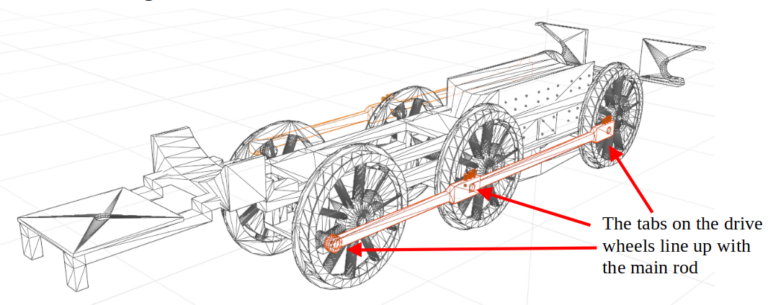
Each wheel has a nub opposite the counterweight. The main rod connects at these three locations so the nubs need to line up together. Both sides need to be confirmed.
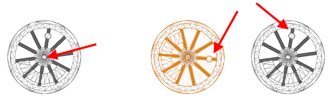
When everything is aligned, fasten the main rods to the wheels. This is best done with the assembly set on a section of narrow gauge track. Do not glue the wheels to the frame just yet. It may be easiest to fasten the rod to the #2 driver first. The rod should be parallel to the frame and boiler.
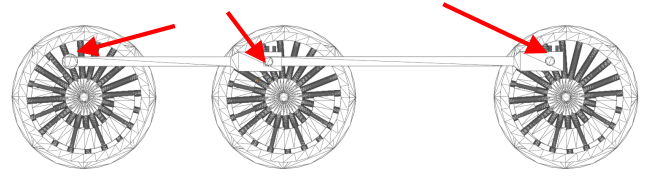
The wheels should float up and down in the frame assembly when the main rods are connected. The wheels shouldn’t be able to rotate.
To align the main rods requires a dry fit of the steam chest and drive rods to define what position the wheels should be in. Since the valve slides are fixed in place, the drive wheels need to be oriented such that the drive rods fit as shown: one end to the inside of the slide; the other fastened on top of the main rod as shown below. The nubs at the end of the rods should be on the up side.
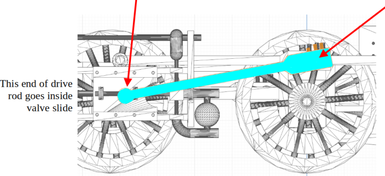
Do not fasten the drive rods until the steam chest is in place.
Step 6: Steam Chest, valve guides
The steam chest and valves are one piece. It would be best to have these pieces painted before this assembly. The steam boxes would have been colored and decorated. The guides and rods would be greased steel.
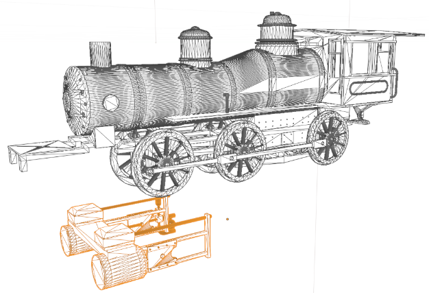
There is a wide slot in the frame for the steam chest. This is where glue should be applied. Make sure the valve slides are parallel to the frame.
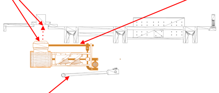
Note the positioning of the drive rod. Since the rod is applied to the inside of the valve guide, there is a little slop available for positioning. The small nubs on the rods are oil nipples.
Step 5b: Drive Rod Assembly
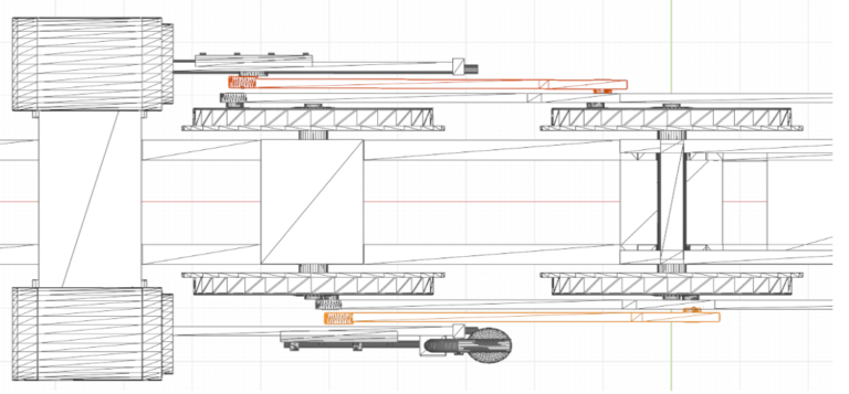
Once the steam chest is in place, the drive rods can be fastened in place. One end glues to the steam chest assembly – inside the valve slide; the other attaches to the outside of the main rod of the center drive wheel. Note the two sides are aligned 90 from each other
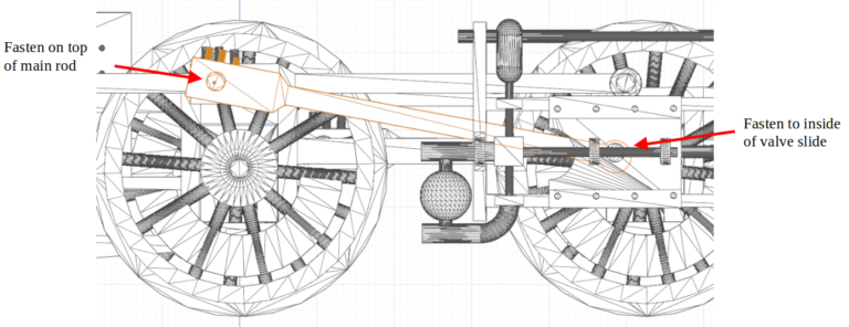
Note that minor adjustments can be made if drive rod is placed not exactly in the center of the slide From underneath, the drive rods are arranged as so:
While set on a piece of track to assure all is level, place a drop of glue on the drive wheel axles. All three should be glued at the same time.
Intermission
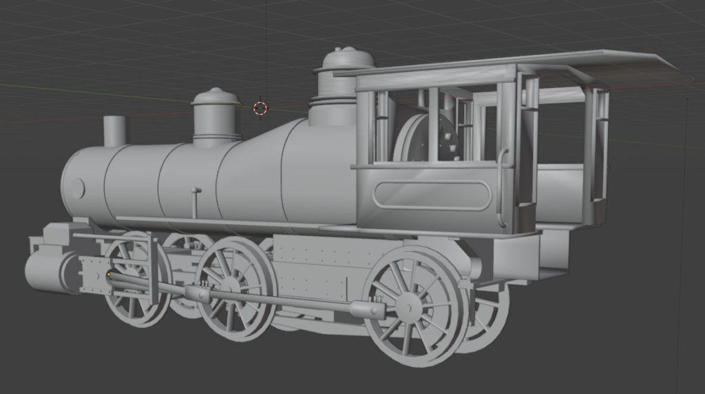
The partially assembled engine should now look something like this
Step 7: Pilot Wheel
CAUTION: The frame on the pilot assembly is very delicate
The pilot wheel has a pin that fits through the hole in the front of the upper frame.
This pin extends above the frame on purpose. This pin sticks up on the prototype as well (apparently a shock-absorber)
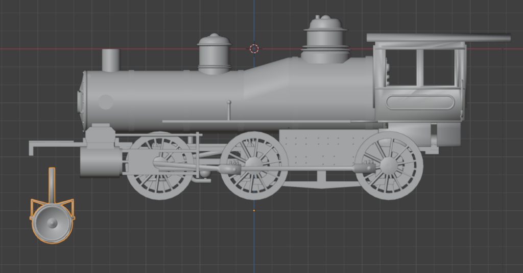
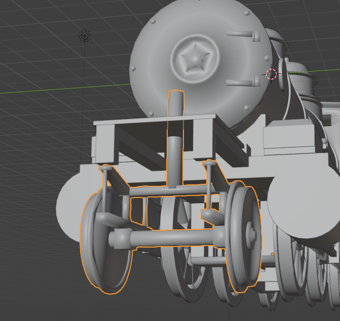
With the engine on a section of track (to assure the wheels are all even and level), put the pilot wheel assembly in place and put a small bit of glue blob on the upper side of the frame to represent the fittings on the prototype.
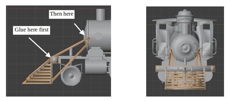
Step 8: Pilot
CAUTION: The support rods are very delicate
These older engines had large prominent “cow-catchers” with link & pin couplers on the front. With the engine on the track section, place a scale 2” board between the track and pilot and glue the pilot beam to the front of the frame. The support rods are glued to the boiler … it may be more convenient to wait until the glue on the beam had set first so that the thin rods can be placed without moving the pilot.
Step 9: Bell
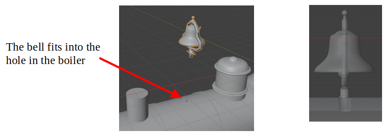
CAUTION: The bell is very small and very delicate
The bell frame is extremely delicate but there should be no problems if handled carefully. The bell itself would be brass; the frame would probably be the same color as the boiler. The bell fits it a hole on top of the boiler; it might be a loose fit. Make sure the bell frame is even across the boiler and sits vertical.
Step 10 – Stack
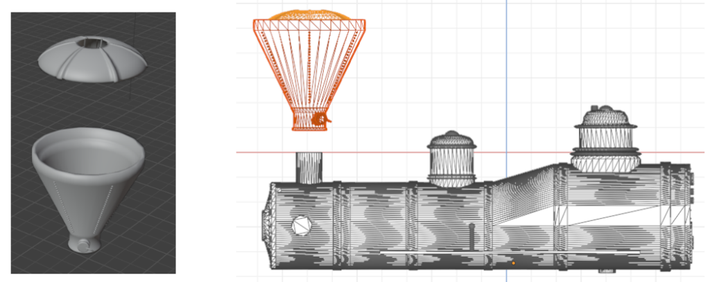
Attach the ash screen to the stack; it should be a press-fit (but should be glued in place). This screen would be ash colored; I used adamantine black on this piece with possibly a dark grey over-wash. The stack will fit nicely over the nub on the boiler. Make sure the stack stands straight. Glue in place. The clean-out is on the left and points slightly to the rear
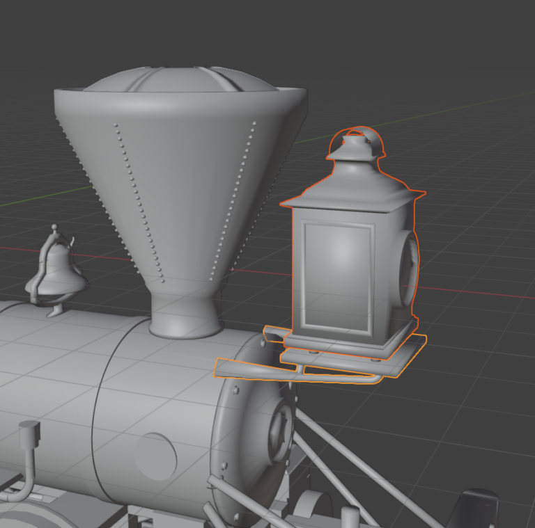
Step 11: Lamp
CAUTION: The lamp bracket is very delicate
Fasten the lamp to the lamp frame. This may be a bit touchy getting the lamp to sit on the 4 nubs long enough for the glue to set.
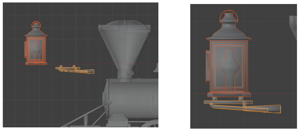
When the glue has set, carefully fasten this assembly to the boiler. There are small notches in the boiler to guide placement. Again, assure the lamp is level while the glue sets. This is a difficult placement so care is necessary. Gel superglue is useful here. Sets fast but a few seconds are available for tweaking the placement.
This is a “ready, set, go” gluing process. Easy to break, easy to make a glue mess.
Step 12: Piping
CAUTION: The pipes are very delicate
A few more steps finalizing the model:
There are three pipe pieces to be added:
A hose from the air pump to the cab. One end of the hose is fastened to the center of the upper half of the air pump; the other side to the cab wall next to the boiler.
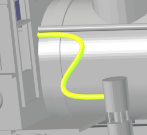
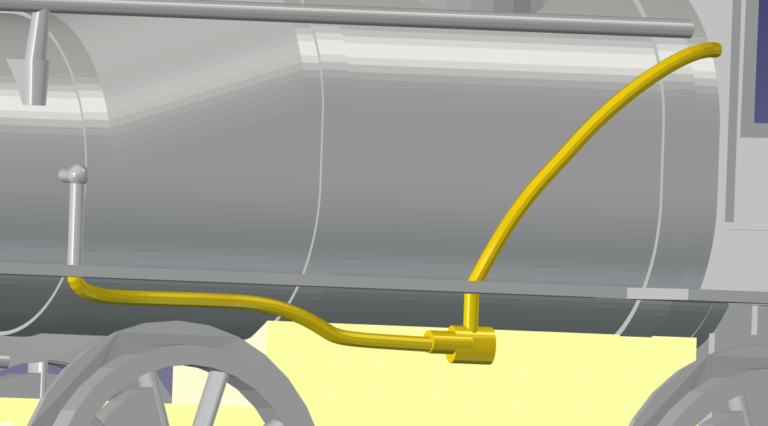
On the left side, there are two pieces to add. They represent a single pipe.
The underside pipe is placed under the running board on the left side of the boiler. The front of the pipe lines up with the cylinder on the boiler. The pipe rides up against the running board and boiler with the rear end up against the running board far enough from the boiler that the upper pipe will appear to be the same pipe. The upper pipe can rest against the boiler with the rear end “entering” the cab.
Step 13: Handrails
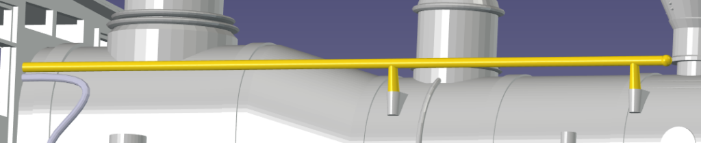
Finally, two hand rails run along the boiler as shown. The stand-offs on the rails fit the holders on the boiler. There is a slight tilt outward on both.
This completes the engine assembly.
These last fittings on the boiler are delicate. Handle the engine with care.
TENDER
Painting. Depends on the color scheme. In many cases, the tenders were decoratively painted. If all one color – perhaps black – wait to paint until the pieces are assembled. If the tank is to be colored differently from the frame, paint now. The frame is likely black.
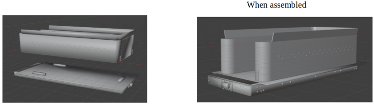
Glue the tender tank to the tender frame. The nubs should provide a comfortable fit but make sure the tank is aligned with the frame
There are no couplers. What type? link & pin (as the original), knuckle, ??? User’s choice. Are they even needed for the scene intended?
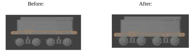
Next, align the tender trucks with the holes in the frame and fasten. The trucks are not intended to rotate. This assembly should be set on a flat surface – a piece of track perhaps – to assure the wheels line up with the track.
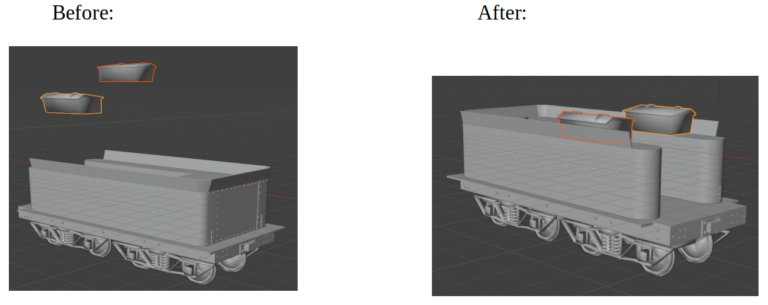
The procedure for the toolboxes is similar. The lids would open towards the inside.
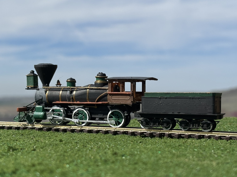
And the model is now complete; ready to fill in that background scene.
Contact us at info@PayetteValleyModels.com