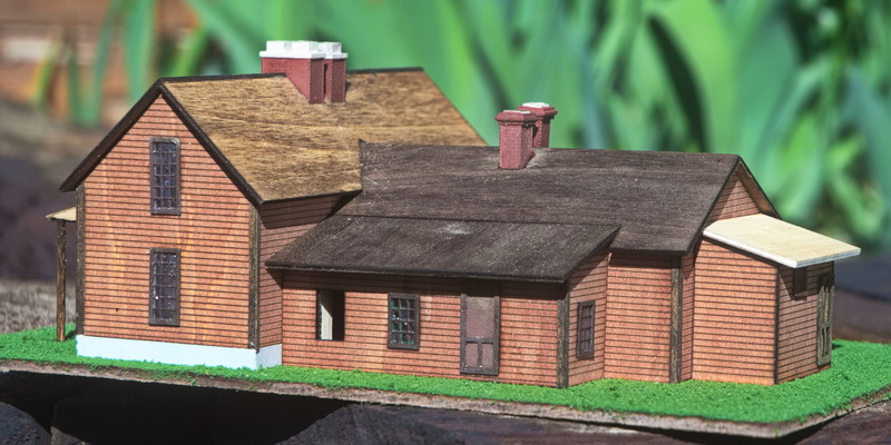
The name “T-House” comes from the shape of the original footprint. Although there are no windows or doors cut into the back section walls of the kit, the structure can be completed with the original footprint by leaving off the additions and mud room. It was a duplex and fixtures would have been mirrored on each side.
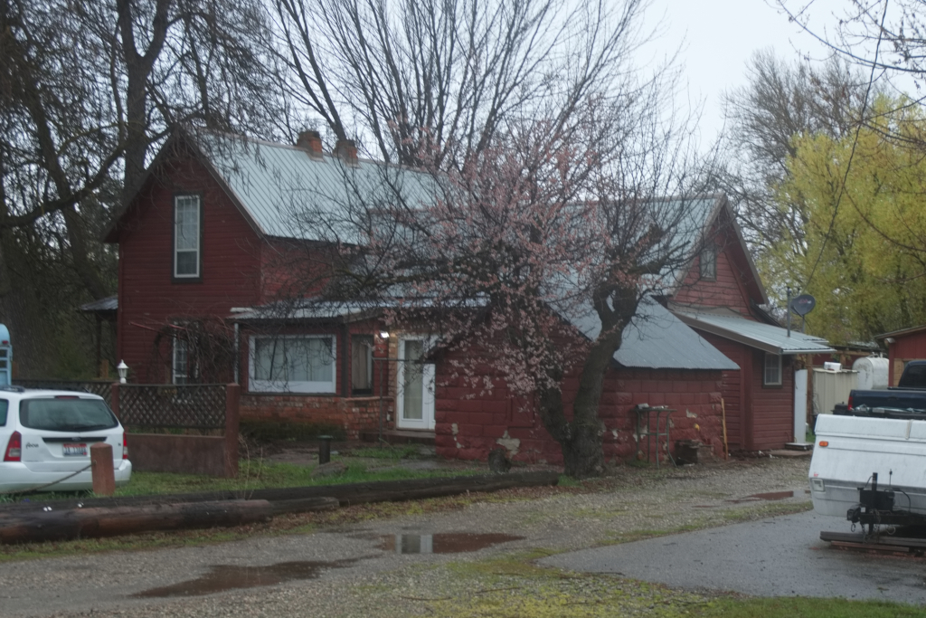
Built as a duplex in 1910, this structure now exists as a single family residence. Currently listed as a 2000 sq ft, 4 bedroom, 2 bath residence, later additions have been added to both sides of the back section increasing the structure from the original 800 sq ft for each side.
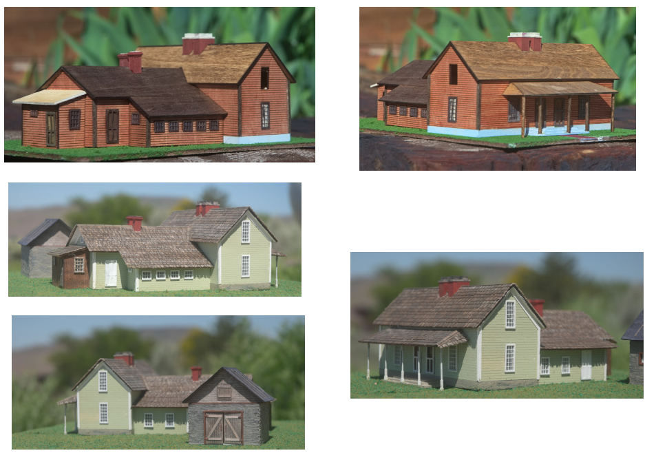
The present structure is barn red with brown trim and white doors and window frames. The roof is grayish corrugated tin. The original color is unknown – perhaps as it is now; the roof was originally wood shake.
The kit includes a sheet of uncut acetate for glazing but does not include roofing material; these are individual modeling choices. The original roof was shake shingles; it is now painted corrugated tin.
T-House Parts
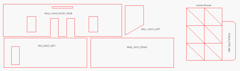
The unlabeled laser-cut parts are identified here. The etching of these walls is not shown; the labels are not printed on the etched parts.
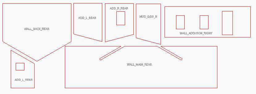
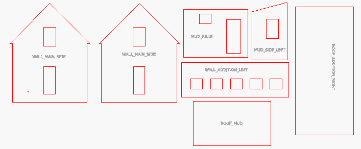
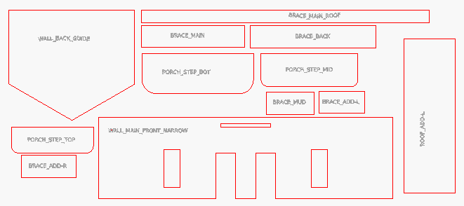
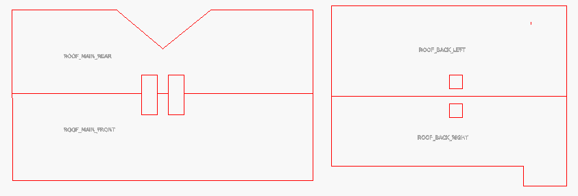
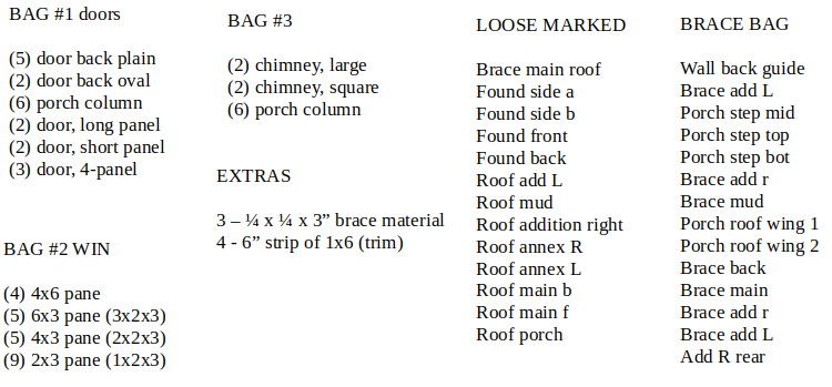
The remaining parts are bagged as follows:
PREPARATION The structure is built of laser-cut 1/16” plywood. 1/16” is equivalent to 5.44” in HO scale – roughly the thickness of the prototype wall. Windows and doors are 3D-printed resin. While somewhat fragile, this material may be sanded or drilled as desired. Use proper ventilation when sanding or painting.
Arguments can be made for various methods of preparation. Prepare/paint the walls before assembly. Or, assemble common parts then paint the assembly. Or, just build it and spray paint the whole thing when done ….
The construction steps used for kit development are presented; the modeler can apply an assembly method of individual choice.
The thin wooden walls tend to warp when painted or stained. Using an alcohol rather than water-based thinner reduces the swelling but if warped, wet one side of the wall, place on a flat surface and weight the wall down until dry. Be careful the flat surface does not cause stains or marks on the wall. The interior is not intended to be visible; bracing across the grain will help keep the walls flat.
Wood construction glue such as Tite-Bond is used for wood-wood connections. Gorilla Glue works well for fastening the printed resin parts, regular 2-part epoxy also works well for the resin parts. Superglue also works with the resin parts but the resin is not styrene – most “plastic” glues will not work (including MEK).
I’ve not had good luck with double-sided tape – if I make a mistake, I’ve found it difficult to fix without causing damage. I use Aleens Tacky Glue or a wash of 1:1 or 1:2 white glue (Elmer’s) to water as “paint” and fasten whatever roofing with that. Other methods also work. While the base roof is supplied, the roofing material itself is not.
[The symmetry of these pieces allows a structure to be constructed without the etching on the outside walls. The only difference to the structure will be the left and right location of the two side additions – which are not identical]
Construction
PART 1 – MAIN STRUCTURE – The top part of the “T”
There are two front walls included with this kit – one with narrow windows, one with wider windows. The present structure has asymmetric windows – the original 3×6 pane on the right; a larger 4×6 equivalent .
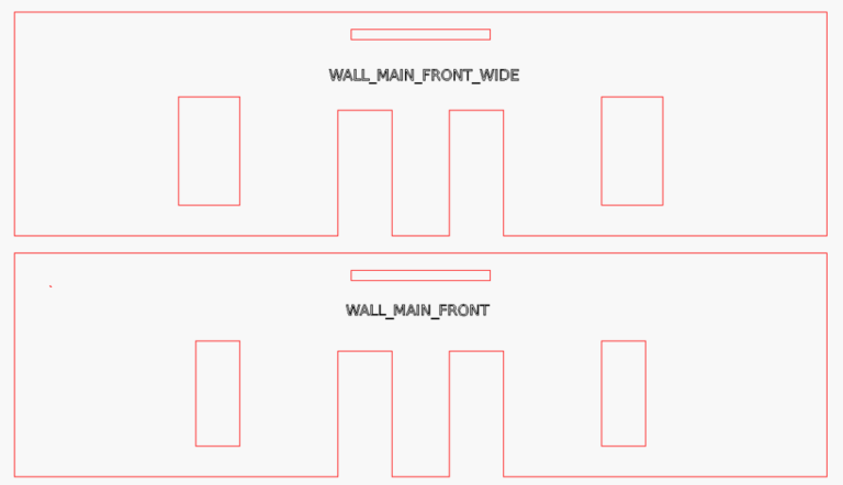
If choosing to model the “modern” version (with different-size front windows), first modify the front wall with narrow openings by enlarging the left window opening.
Both size windows are provided; to model the current structure will require trimming the left-side window of the narrow-window wall to fit the larger size window.
There are two sections of bracing intended to keep the walls from warping when painting or staining. Put one across the front wall just above the door openings; place the other across the backwall close to midway up.
Paint or stain all walls as desired. Paint resin pieces as desired.
Fasten doors and windows to walls. This will require a glue appropriate for the resin parts: superglue, gorilla glue, or epoxy work best.
Fasten the side walls to the front and back walls – one method is to fasten one side wall to the front wall using some means of assuring a 90º angle – a small picture frame jig and/or machinists squares help. The other sidewall is fastened to the back wall in the same manner forming two sub-assemblies. The slots on the back wall are on the upper side.
Triangular corner braces are also provided. If so desired, these may be placed in such a manner as to support a second floor. However, the interior is not designed to be visible and the material for a second floor is not included. The braces should still be used but the vertical placement would not be critical.
The front and back walls fit inside the side walls. Some ¼” x ¼” material is provided for additional corner support. Something close to ¾” should be sufficient and still allow room for the 2nd floor supports (if desired).
Looking from underneath:
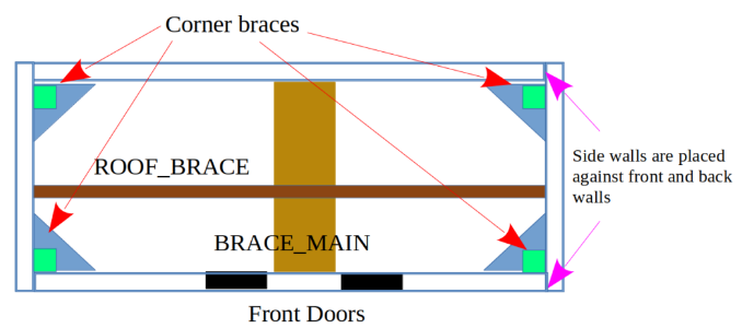
The brace pieces add strength, lessen warping, and assure proper spacing. Cut sections of the 1/4″ brace materials to fit into the corners. Make sure the brace will overlap the wall and foundation.
Referring to the parts illustrations, the BRACE_MAIN will fit between the front and back walls – it is laid flat and centered above the foundation and between the doors but vertical location is not critical.
With the two corner sub-assemblies combined, add ROOF_BRACE between the side walls. Make sure to leave clearance for the chimneys – the brace should not be at the peak. (or cut a slot in the chimney to accommodate the brace).
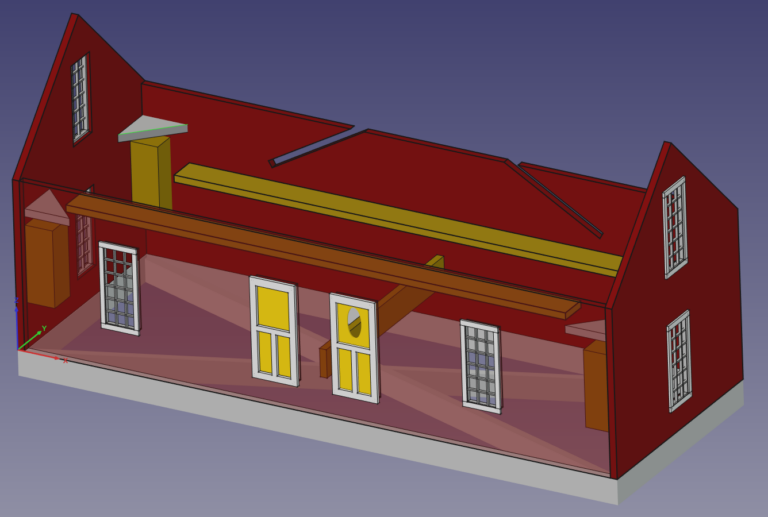
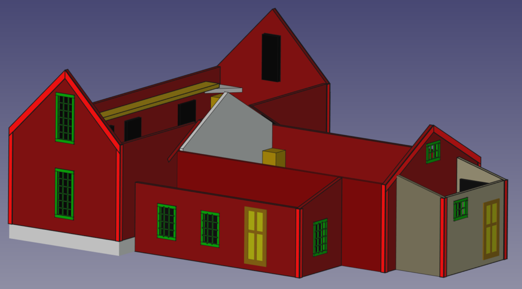
At this point, the structure should look something like this from the front – assuming the walls are painted with windows and doors installed but no trim.
Rear Section
With the main assembly sitting on a flat surface, place the wall piece labeled “WALL_BACK_GUIDE” against the back wall. The bottom of “WALL_BACK_GUIDE” will sit on the flat surface – there is no (visible) foundation to the rear section – the prototype yard slopes toward the front; the foundation is exposed in the front and sides but is buried to ground level at back.
The top edges of the wall should be flush with the slots on the rear wall of the main section. The roof pieces will fit into those slots.
Reversed clothespin clamps work well to assure the guide wall is fastened flush to the main rear wall.
The back guide wall is not visible in the final model; it may be used to experiment with coloring methods.
Fasten the two sidewalls and rear back wall together in a manner similar to that used to fasten the main assembly walls. The left side wall has the door opening. The rear wall fits against the sidewalls as shown. Bracing as in the main assembly can/should be used in the corners.
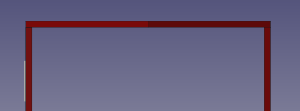
Fasten this assembly to the rear wall of the MAIN assembly. The sidewalls fit against to the rear wall of the main assembly and against the sides of the guide wall.
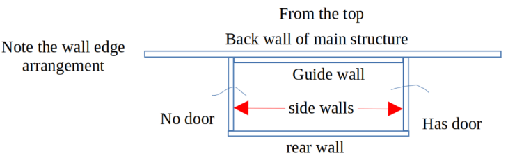
The sidewalls do not come to the top of the vertical edges of the guide wall.
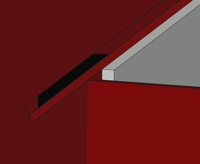
There is a 2nd guide wall to be placed between the two walls. It holds the walls apart at proper spacing and supports the roof. Placement is not critical but about halfway along the length is a good position.
ADDITIONS
At some point, additions were added to the rear section of the house.
Fasten the long and short walls together as was done with the previous walls. Braces are provided which will act as spacers for each side. With the braces against the main back wall, fasten the addition sections in place. Clamps and weights come in handy.
Fasten BRACE_ADD_L to the right side (from rear) of the main structure rear wall and BRACE_ADD_R to the left side rear wall of the main structure. The etched lettering will face the rear wall.
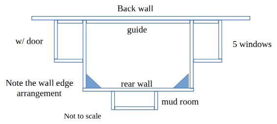
Mudroom
The final major sub-assembly is the mudroom. There is flexibility here; the end wall can be placed inside the sidewalls as shown above – or bring the sidewalls in a bit and place the end wall against the sidewalls. While shown above as centered, placement along the rear wall is arbitrary (the mudroom is towards the left side on the prototype – as it stands today. The mudroom likely didn’t exist on the original.
If the choice is made to leave the mudroom off, openings in the rear wall need to be prepared as it is likely the original had two symmetrical rear doors along with two symmetrical windows. Using the window and door intended for the mudroom, an extra door and window are included in the kit for this purpose.
At this point, the building should appear similar to:
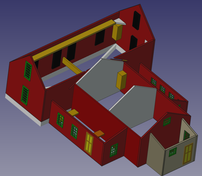
Trim
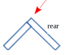
Once the walls are in place, the trim should be added. Note the walls are a scale 5.4” thick – a scale 1×6 is barely sufficient to cover the edge so placement of corner trim needs to be as shown. The trim is placed such that the wall edge is covered and the non-edge side overlaps the end.
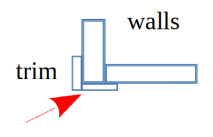
Aleens Tacky Glue works very well for applying trim. Smear a thin layer on the trim pieces and press in place. The glue will hold it but allow a short period of time for adjustment. It will hold firm though; it will be very hard to remove the trim once the glue has set.
There are 20 pieces of 1×6 trim for the corners and 6 pieces of 1×8 for the roof trim. These should be trimmed to fit. There is no trim over the foundation. Clothespin clamps work well to hold the roof trim pieces in place while the glue sets.
ROOFS
The prototype roof is now metal, ridged at 12” intervals. It was originally a shake roof – being located in a lumber mill town. It was not a premium dwelling but a tarpaper roof was unlikely … although in that place and era, it could be possible. Shake shingles would be more appropriate.
Roofing material is not included. Wild West Scale Models has a nice selection of shake roofing; other possibilities exist depending on the modeler’s preference.
The roof sections are 1/16” thick – 5.44” scale inches. This is roughly the thickness of the prototype roof when rafters are considered.
Place the rear sections of the roofs first. They fit into the slots in the rear wall. It may be beneficial to bevel the back section roof edges to a 60º angle (the front roof sections meet at a 90º angle). The right-side addition roof will need to be feathered at a sharp angle so not leave a ridge at the joint between the two sections.
Roofing material will cover any small gaps between the roof pieces if the edges are not sanded; a ridge cap will cover any gap at the peak.
Once the rear roof sections are in place, the main roof sections are placed. These sections join at a 90º degree angle; one method of fastening the sections is to treat them as walls and join them as any 90° joint … then place the roof assembly in place. Test fit before committing to this method though
The rear section overlaps the front section.
When fitting the main roof pieces, make sure the holes for the chimneys line up …
The other roof sections may be added at this time. Bevel edges are desired. It’s best if the trim has already been placed.
The mudroom roof fits directly on the mudroom walls. Make sure the roof is centered.
PORCH
At this point, the model should be placed on a base. The three “concrete” porch sections are stacked and placed centered against the front wall foundation. Like the prototype, the top step does not line up with the front doors thresholds. However, the height may be adjusted as desired.
The porch roof and posts are 3D-printed. The porch roof material should match that of the main house section.
There are 5 porch columns on the prototype: three short ones placed on the bottom step; two to either side, one centered between the front doors. The other two are placed at the corners of the porch roof and stand on “ground”.
Final Details
There are three 3D printed chimneys to be placed: a double flue is placed in the hole of the main roof. A “fancy” one is placed in the right side hole on the rear section and a plainer one on the left side.
Finally, a smokejack is placed in the mudroom roof.
The structure is now be ready for placement, scenery, and desired weathering.
Roof covering is up to the modeler. The prototype had shake shingles; later asphalt, now corrugated metal. Corrugated tin may be used; one of the kit prototypes used “tar paper” as covering. Wild West Scale Model Builders is one supplier offering a nice set of shake shingles – the kit prototype used similar but different colors on the main and rear sections – WildWest #2 and #8 – but of course, the choice is the modeler’s.
This completes the assembly of the T-House.
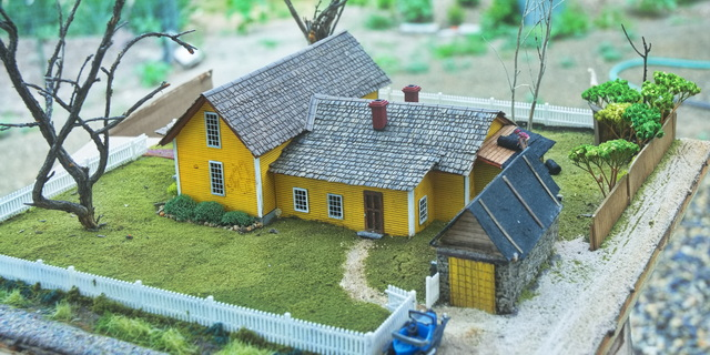
Landscaping, fencing, and other details not included in kit
Final Details (Optional Garage)
The garage is a mix of 3D-printed walls and wood. The prototype is also of 1910 era and is of a size that reflects that – too small for modern vehicles. The walls are intended to be of rock construction. The one window is printed into the walls.
The walls should be painted to reflect field rocks of a base color reflecting the region the model is to occupy.
One draft version was painted with a base wash of FolkArt’s “Barnwood” sloppily applied. Let the base coat thoroughly dry before applying additional coats. Various washes of various grays and lighter browns – 1:3 – 1:2 alcohol or water to paint – were sloppily applied until a desired color variation of the walls was achieved. 4 or 5 coats may be sufficient.
The window should then be painted. The frame would be either bare wood or painted. The front and back door frames printed into the walls should be painted before the doors are added.
There is also a wood frame printed along the top of the walls that should be painted.
The main door comes in two pieces; they open from the sides. They are constructed from 1×6 or 1×8 as desired with Z-bracing made of 1x6s. The back door is also made of 1x6s.
The front and rear gables fit against the tabs printed into the walls. Paint as desired before fastening to the walls. A roof beam is placed between the two gables.
When all is prepared and ready, place the two roof halves in place. When dry, roofing should be applied. Tarpaper is an acceptable option for the garage although shake shingles would more likely be original.
That’s it …
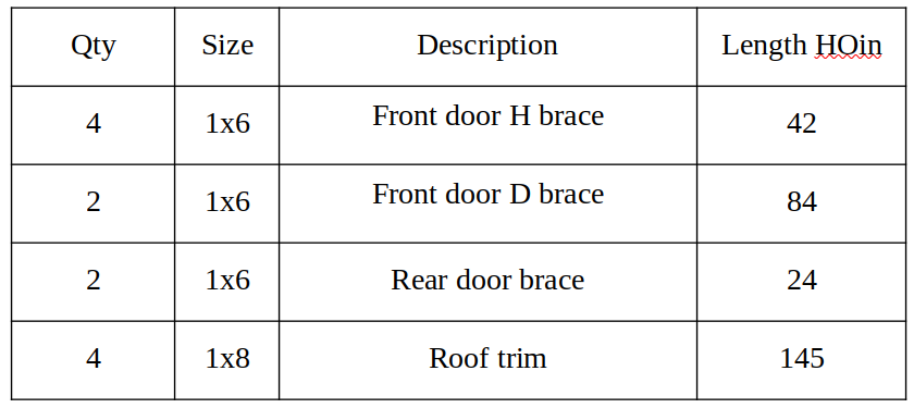
Lumber Pieces – Main House
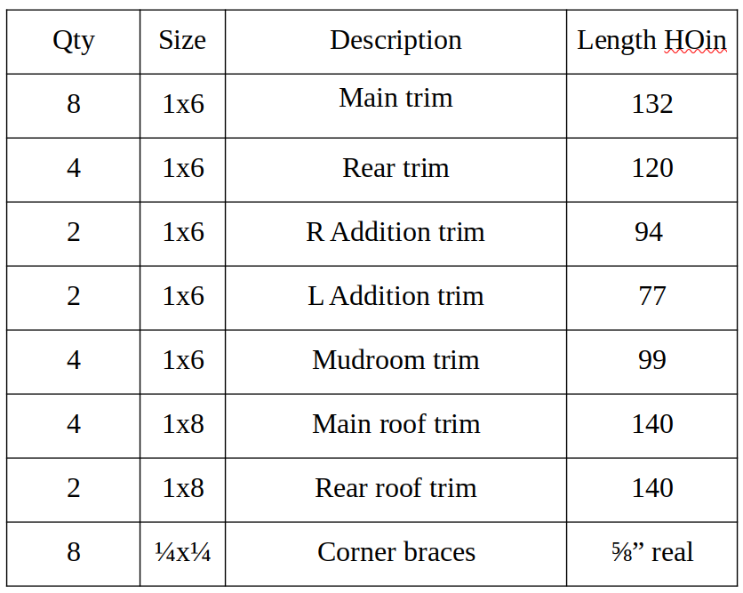
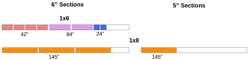
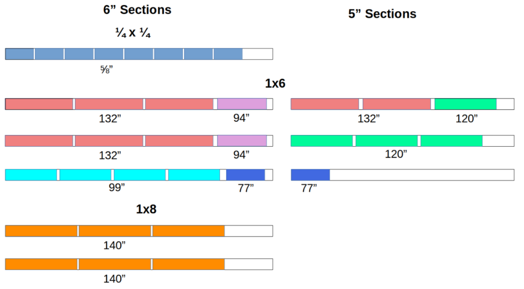
Suggested Lumber Cut Guide
Roughly to horizontal scale. Suggested cuts for 6” and 5” sections of lumber.
Only cut lumber to fit actual model pieces.
Garage
Suggested Lumber Cut Guide
Roughly to horizontal scale. Suggested cuts for 6” and 5” sections of lumber.
Only cut lumber to fit actual model pieces.