Pearl General Store
Pearl, Idaho was a mining town about 20 miles north of Boise … or four or five hours by wagon. At the extreme western edge of the Boise Basin mining district, a bit of gold was discovered in 1867. Later discoveries led to the formation of the Willow Creek mining district; the town of Pearl was formed in 1894. At its peak in 1906, Pearl boasted of 3 general merchandise stores, a butcher shop, 4 saloons, 2 hotels, a church, fire station, an Odd Fellows Lodge, and perhaps 2,000 people. But the mines were mostly played out by 1910 … and so was the settlement of Pearl. Nothing remains at the site today, not even foundations.
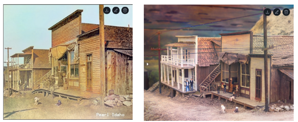
The original inspiration to develop the Pearl diorama was this 1902 photo taken in the heart of downtown:
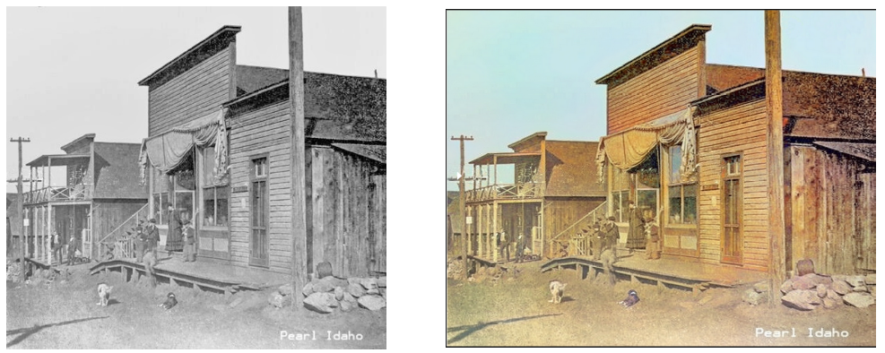
Further photo processing suggests the hotel front was white, the general store awning faded red, with cream yellow front and dark red or brown trim. Shake shingles and bare wood on the sides. It is possible the general store false front was bare (new) wood with brown or dark red trim with a white and brown front entry. The lady’s dress appears black or dark blue. The most productive mine, the Checkmate, was directly across the street.
This was the main corner in town; one branch cut off to the right and uphill to mines, the other came straight through as the main route south and east.
It was a natural decision to offer both structures as kits.
Construction
Painting and Colors
Start construction of the Pearl General Store by painting the resin front entry in colors desired. On one draft kit, DecoArt’s “Buttermilk” and Ceramcoat’s “Red Iron Oxide” were used for the resin entry with the wooden front walls done with thin washes of FolkArt’s “Sunflower”.
Varathane’s “Early American” oil stain was used for the side and rear walls – the stain was applied after the walls were assembled but before the windows were placed.
The resin parts will require at least two coats. It is best if multiple coats of a thin wash is applied; it helps maintain the detail: a mix of 30 – 50% alcohol or water to thin the acrylic paint works well. Air-brushing the base coat (Buttermilk) on the resin front entry may work well but a very fine brush should be used to apply the trim color (Red Oxide). A 3/0 or 4/0 brush and steady hand may prove best suited for this.
Paint the wooden front walls at this time: the false front of the main building and front wall of the Annex. Multiple coats of a thin wash of “Sunflower” were applied to the draft model. An undercoat stain of IA may be considered. There is no room for cross-grain bracing on these pieces; place the pieces under weights to keep them flat until they dry – be sure the contacting material doesn’t damage the painted surfaces.
The interior will be visible due to the large front windows. Paint the interior side walls a desired color – the draft kit used washes of Vallejo’s “Off-White”. Because of the visibility, it is not feasible to brace these walls against warping so, like the front walls, place the pieces under weights to keep them flat until they dry. Do not paint the exterior sides at this time.
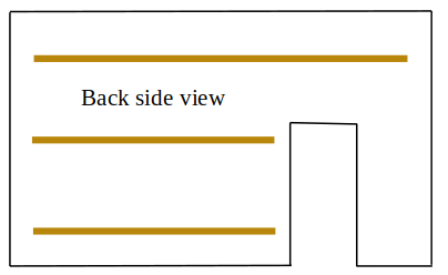
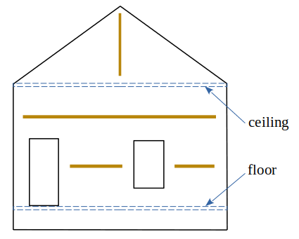
There is an interior rear wall included. The front side has an open doorway with etched door trim and beadboard. Place bracing on the back side across the top above the door opening, place two more lower down next to the door. The bracing should not extend to the wall edges; leave room for the corner braces.
Color as desired – there is no prototype information regarding interior colors (and only guesses about exterior colors). One draft model interior had off-white walls with white trim and “English Chestnut” oil-stained (etched) beadboard. The stain is carefully applied to minimize bleeding. When dry, the etched trim-work is painted (and cover any bleed-over oil stain).
The ceiling and floor should be colored at this time: different color oil stains were used on the draft model. Anything from near-black walnut to light maple would be feasible. The ceiling is etched as lumber rather than tin tiles; with tin tiles, a ceiling of white or “tin” would be appropriate as well.
((Ceiling fans would be appropriate as well: the town had electricity and this was the fanciest establishment in town.)
The underside edges of the roofs will be visible. These would probably be bare wood on the prototype; color the underside and edges as desired. Depending on the style and technique for roofing, it may be desirable to color the top sides of the roof pieces as well. The top sides have etched shingle guides spaced 6 scale inches apart.
The windows on the sides and rear would likely be unpainted wood or painted with a white wash. Actual White may be a bit strong, Vallejo’s “Off White” (70820) is used to color the window frames. It is unlikely the rear doors would be painted so something approaching a “wood brown” should be used to color the resin doors. Again, at least two coats of coloring provide good results.
One “experiment” involved dipping the resin frames into an oil stain. It leaves a glossy shine which can be rubbed out. Another possibility would be to overcoat the stain with powdered chalk (such as one or two of Rembrandt’s umbers and siennas)
Actual color choice is up to the modeller.
Glazing
Cut out pieces of acrylic sheeting to fit the windows; both in the entry and the side windows. A glue that dries clear is best: most glues have trouble adhering to acrylic – but Zapf Creation’s 560 Canopy Glue is a good choice. One technique for the smallest windows is to use the 560 glue to fill in the window frames and let dry. The result has a clear but “old glass” look. The top-most “trim” windows were colored with Tamiya clear yellow (81024).
Do not place the side or rear windows just yet.
Awning
This step may be skipped if the awning is not desired but should be done first while the resin front entry piece is available for fitting the awning supports.
Epoxy or solder is suggested to assemble the awning supports. There are 4 nubs on the front face of the entry which act as the base for the awning support rails.
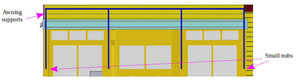
Using the entry nubs as guides, cut (to fit) four 6’ (about ⅞”) lengths of the metal wire provided and a longer length (not quite 2¾”) fitted between the two end rails. Epoxy or solder these five pieces together.
Set this aside until near the end of the assembly process
Main Walls Assembly
The first step of assembly is to attach the Annex front wall to the right side of the entry.
Note: the kit may be assembled into different configurations – without the annex or attached shed.
Skip this and related steps if the annex is not to be added.
However, the instructions will include both
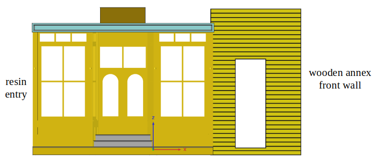
There is a lip formed by the right-side trim on the resin entry. The annex front wall fits behind that lip as shown below. Place a thin layer of glue (gorilla, epoxy, or super) along the inside of the lip and place the annex wall into place. Make sure the bottoms are even with each other and the side edge flush with the lip. If the entry is placed flat on a surface, using a piece of 1/16 scrap under the annex wall will help the wall fronts remain even. There is no bracing on the annex front wall.
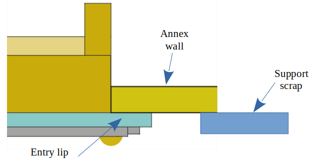
Next: This subassembly is fragile while placing the walls until all walls are added.
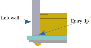
Next, the left side wall is attached to the entry.

There is a similar lip on the left side of the entry; the left wall fits into it as shown. Place a thin layer of glue along the lip and place the wall as shown. Again, make sure the bottom edges line up. A 90° square will help assure the walls are at right angles.
Place braces on the rear wall as shown (view from the inside):
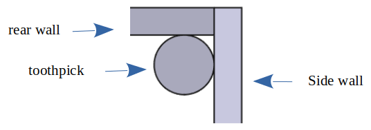
While waiting for the glue to set on the left wall/entry, fasten the main right wall and rear wall together. The right side wall butts into the rear wall; the bottom edges should be flush with each other.
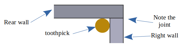
A short piece – 1” or so – of toothpick should be used as a brace in the corner – but room needs to be allowed for the floor and ceiling … so the bottom of the brace should be at least 30 scale inches from the bottom and 6 from the top. Other than clearances, placement is not critical.
With the walls set flush on a flat surface, place the floor supports along the wall bottoms
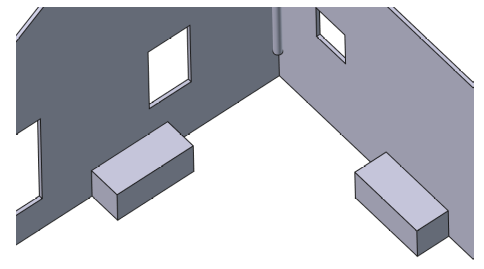
The supports should be roughly centered along the rear wall and about ⅓ of the distance from the rear wall along the right wall.
When the entry/left wall assy is dry, another floor support is added along the left wall.
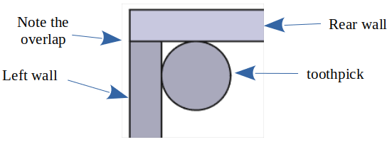
When these assemblies are ready to be handled, fasten the left and rear walls as shown. Use a section of toothpick for a corner brace: 30” minimum from bottom, 6” minimum from top.
The left wall butts into the rear wall as with the right wall; the right wall will butt into the annex front wall/entry assy.
Do not glue the right wall to the entry at this time; flexibility is needed to place the floor.
There are ledges on the interior of the entry piece:
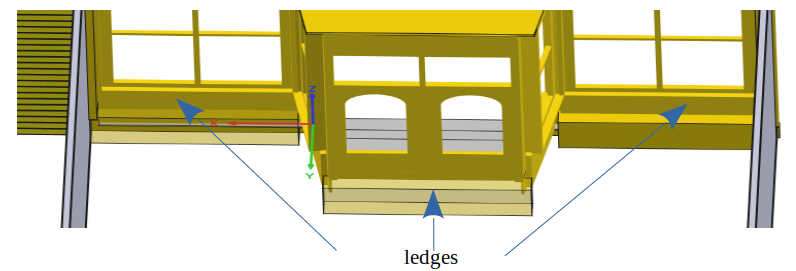
Make sure the assembly sits on a flat surface. Dry-fit the floor in place. The floor has a notch to fit the entry; place the floor front edge onto those ledges and on top of the floor supports on the side walls. The floor should fit snugly but not tight. Make sure the floor fits firmly on the floor supports.
Do not glue the floor in place yet.
The placement of the interior wall is not critical but should be about ⅔ towards the rear. With the floor in place, set the wall where desired, making sure it is at right angle to the walls and vertical. Place a toothpick section as a corner support on the back side of the interior wall where it joins the left wall. Recall this interior is visible through the large display windows.
With the floor and interior wall in place, fasten the right wall to the entry/annex wall assy. A slow-set glue (gorilla glue works well) applied to the lip will allow “tweaking” of the wall placement. Make sure the assembly sits even on a flat surface.
The right wall will fit into the entry/annex assy as shown:
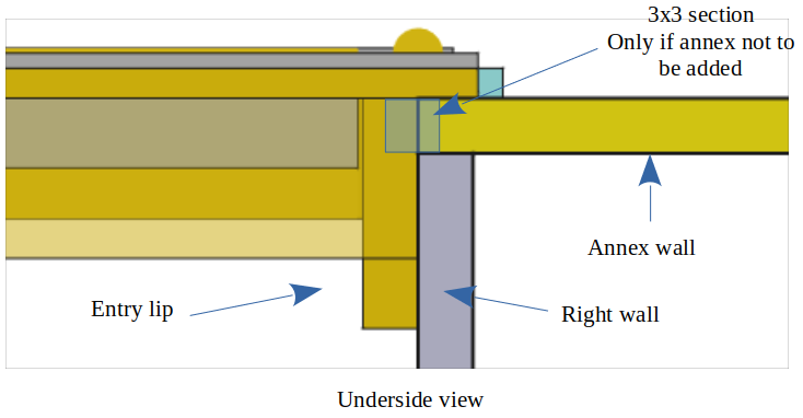
Note: if the annex is not to be included, cut a section of 3×3 the length of the height of the right wall and place it into the lip where the annex front wall would be. Then attach the right wall as instructed.
Place another toothpick section as a corner support on the back side of the interior wall where it joins the right wall.
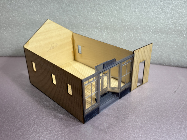
The model – without ceiling (and without the interior wall) – should now appear similar to this:
From underneath, place a bead of wood glue along the floor edges and place a floor support to the center underside of the floor where the interior wall crosses.
The ceiling is made of 1/32” wood. “Decorative” wall bracing will be placed about halfway between the front and interior wall between the front two side windows. An identical brace should be identically placed on the right wall. These are made by cutting sections of 8×8 lumber to fit between the floor and down-side of the ceiling: 1/32” less than the distance from floor to top of wall.
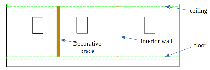
Color the beam appropriately for the interior, it will be visible – a medium brown stain (Minwax “English Chestnut” was used on the draft model). When dry, fasten to the walls; use clamps to make sure the beams fit tight against the wall – they act as braces for preventing wall warping when the walls are colored.
Dry-fit the ceiling in place: at the top but between the right and left walls. Now that the walls and floor are firmly in place, the wall exteriors can be colored. The draft kit was colored with an oil stain (Varathane “Early American”) applied with a piece of rolled paper towel used as a brush. Light coats can be swiped on; the stain does not need to be “painted” on. Using the paper as a brush eases clean-up … throw the paper away when done.
Let the stain dry, then remove the ceiling for now.
Annex Walls
Skip this step if the annex is not to be added.
Glue two toothpick braces across the side wall, high and low, and across the rear wall (above the door and window openings). Placement is not critical but leave room for the corner braces.
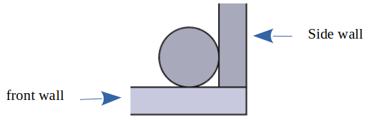
Join the rear and side annex walls. The rear wall butts into the side wall. Use a section of toothpick as a corner brace. A small square is useful in making sure the walls form a right angle.
When the assembly is dry, it is joined to the annex front wall and main right wall, using a toothpick section as a corner brace and the etched boards as a vertical guide.
Windows and Doors
With the walls now all in place and stained/colored as desired, it is time to place the previously colored windows and doors. If glazing has not been put in place, place it now. Canopy glue works well for fastening the acetate pieces to the resin frames. Shades, curtains, and other trim should be placed now if desired.
Interior
It may be desirable to detail the interior: a general store, a drug store with fountain and seating (in the front windows), or some other business. A resin figure representing the sitting “person” staring out the window is included*; there are no other interior details provided. It may be desirable to add lights. As Pearl had electricity at this time (before Boise city!), incandescent lamps may be prototypical. The prototype photo shows a telephone/telegraph pole but no obvious electrical connection to the building is visible.
When the doors and windows are in place and any interior detailing is complete, fasten the ceiling to the assembly. The ceiling fits inside the walls; the top surface of the ceiling should be flush with the top of the side walls.
*Upon later examination of a better resolution photo at the local history museum, it might be that what at first looked like a person, sitting at a table, staring out the window at the photographer may actually be sunlight reflecting off a lamp in a display window. Can make an argument either way with the information available.
False Fronts
What’s a western building without a false front?
There is a piece of etched wood with a large triangular notch cut out. This should be glued to the back of the main false front. The top edges align; weights or clamps should be used to assure a firm fit.
A similar piece is applied to the annex front wall, again clamping to assure a tight fit.
It is important that these two pieces fit snugly; the headers slip down over the top edge and need clearance.
The main false front fits in the grove formed between the sign and the tab of the entry. It should fit flush against the annex front wall.
The bottom edges of the back pieces are guides for placing the roof sections.
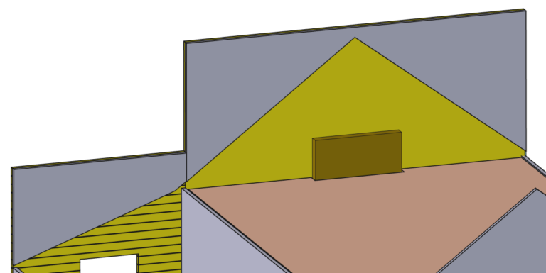
Flat clothespin clamps can help hold the false front piece in place, flush to the sign and against the tab, while the glue sets. Use the etched lines on the front face to align with the top of the sign.
Headers
The headers should slip over the two pieces of false-front. The annex header fits tight against the main front wall
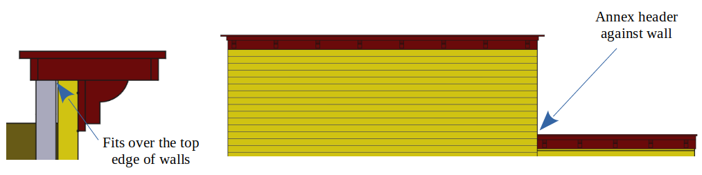
Again, use the etched lines on the wall fronts to align the headers. The tops of the headers should be level with the base
Roofs
The addition of the three major roof pieces will set the straightness of the walls – it’s likely there’s still a bit of twist to the walls.
There is a triangular piece that acts as a roof guide behind the front false wall. Using a roof piece for sizing thickness, tuck the roof up against the cutout behind the main false front and mark its bottom edge. Do this on both sides.
Align the triangular guide with the marks just made and fasten in place. There is now a slot in the false front to hold the roof edges.
There is a notch cut out of the right hand roof. When in proper place, the annex roof will tuck under the annex false front back and the notch in the main roof piece.
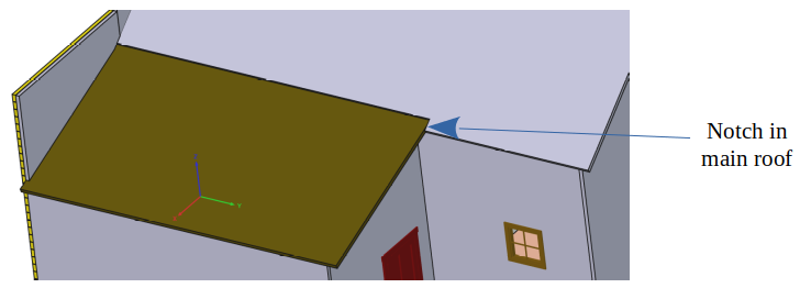
There may be slight play in the annex structure. Work the roof pieces with the walls until all sides are aligned properly. A slow-set glue will allow some degree of adjustment after initial placement.
Some ambitious clamping may be necessary to hold the structure square. Roof overlap should be even along any wall. Use clamps and weights to hold everything place while the glue sets.
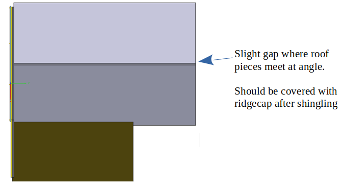
There will be a gap between the two main roof pieces at the peak. This will be covered by the roofing material … or a 1 scale foot wide piece of plain paper can be cut out, folded in the middle along the length, and placed as a ridge cap using Aleens as an adhesive. It’s easiest to do this by folding a wide strip in half, then cutting it down to the desired dimensions.
Trim
Trim should be colored before application. All trim is fit and cut from 1×6 stripwood. Trim locations are shown in PINK. The pieces intended for the front are colored as the trim color; those in the rear are plain wood, colored as the side and rear walls.
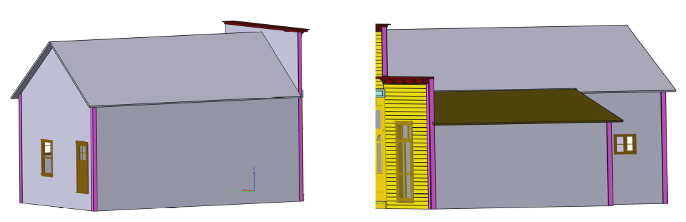
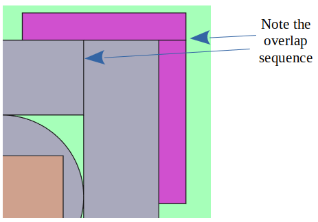
The trim at the corners is set as shown:
The trim boards fit into the headers as shown.
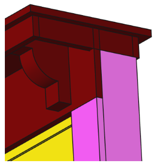
The structure could be considered complete at this point.
Layout & Small Shed – Prototype Study
The final assembly of the structure depends on how it is to be displayed.
Skip if not following the prototype
Per the prototype location (see photo below):
The town was built in a narrow canyon with a small creek flowing through. The road ran uphill from west to east along the north side of the creek. The hillsides rose sharply from the south side of the creek. Between the creek and the south side of the road sat a row of buildings and a few mines on relatively flat ground. The road had been cut through town, leaving the buildings on the north side of the road sitting on a small bluff with the ground sloping upward to the north. The road split at the east side of town, one portion heading straight east to residences and additional mines, the other swinging uphill to the north with businesses on either side and towards even more prospects. The general store sat at the NW corner at the intersection: businesses downstream being lower in elevation, businesses along the cut-off being somewhat higher.
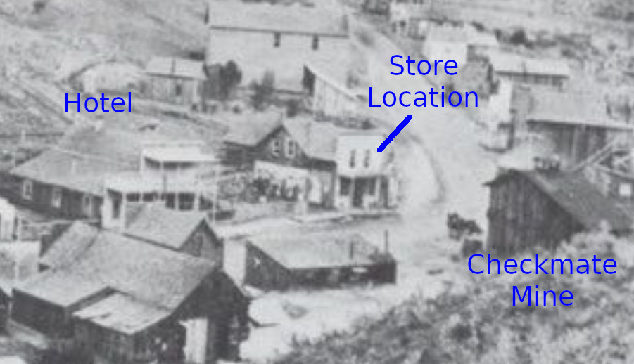
The structure at the corner is not the building modelled from 2 years earlier (1902). However, the hotel in particular as well as other landmarks in other photos verify the correct location. Close examination shows the embankment down to store level from the road going uphill just to the right of the present structure.
Nothing in this photo exists today; even the road has changed: having been shifted about 10 feet south (towards the photographer) on a slightly different approach, the corner eased, and now cutting through the location of the store and the building to the right of the location label. The road going uphill is now a driveway to a ranch gated about where “Store Location” label is and is closed to the public
None of this matters if not trying to duplicate the prototype location. **************** There is a resin “wooden” sidewalk included in the kit as well as a section of “foundation”. The foundation goes under the bottom of the front walls – intended to place the doors of the Cafe at the proper level of the sidewalk.
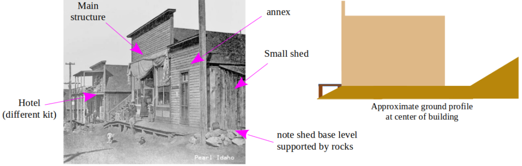
The prototype store sat on a piece of leveled-off ground a few feet above the road at the left side (west), almost at road level on the right-side (east). The road turns north and uphill alongside the right side. Large rocks seem to be placed to protect and support the telephone/power pole with the base of a small shed on the right being maybe a foot higher than the base of the main building.
However, the building may sit flat and the sidewalk is not necessary. In this case the small shed can sit flat as well; the result being the shed roof is lower down the side of the annex wall than shown in the photo.
A better view of the road cut can be seen in this 1897 photo taken just the other side of the hotel building from the photo above
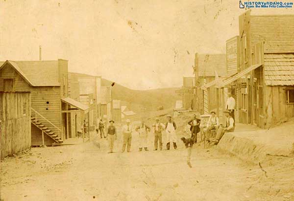
Willow Creek behind buildings to left
Shed
This step may be skipped if the shed is not to be included
Per the prototype, the shed is placed as shown: – about 3 or 4 boards back from the front; up a few inches from the base such that the roof fits slightly under the annex roof. The shed roof may be shake as are the main roofs, but a tarpaper covering is also likely. The roof is etched as 12” boards; 36” wide tarpaper would be laid across them.
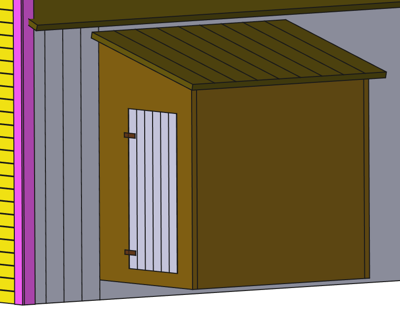
Fasten together the three walls, making sure the corners are square – use toothpick bracing in the corners. The door may be placed open or closed; hinges were made from thin strips of paper – 1/32” is about 3” in HO scale. The shed and door would be unfinished; it can be colored the same as the main building’s sides and rear or simply have several coats of AI applied.
Awning
The support frame was assembled earlier.
Placing the awning itself may prove difficult. Working on a piece of glass seems to help. Placing a sheet of acrylic under may be beneficial; the glue won’t stick to it.
With care, unembossed white toilet paper can work but falls apart easily when wet. A kleenix may prove a bit more tolerant of being wet. If the wetting agent is well-thinned Elmer’s glue, the material will more easily hold together when dry. Apply the desired color to the wetting agent rather than trying to color the material directly. Note that dried Elmers has a slight glossy sheen to it.
There is some evidence the awning was of a reddish hue but a yellowish tint was equally possible as could be a bleached canvas or linen color. The only true conclusion that can be gained from the original photo is that the material is of a lightish – sun-bleached? – color.
With the support rails in a position that the tissue may be worked around it, work the material into a placement that looks natural when placed in position. When dry, carefully place the support rails onto the knobs on the entry face. The awning covers the sign; a thin bead of glue along the sign bottom edge will hold the assembly in place. Using a small dot of epoxy or ACC on the nubs is preferred.
There is no evidence of lettering on the sign board; it may be assumed it was blank or contained the name of the establishment. There is nothing in the records that firmly identifies this structure. A list of businesses is available but the specific locations is not – nor is the list dated. Businesses changed hands and purpose throughout Pearl’s lifetime. What evidence there is suggests this was a general store, drug store, or cafe – or combination. May have served as the post office as well though more likely the hotel.
The final piece to be placed is the back door steps; best to be placed once the model is put on a base.
Pearl Cafe Parts List
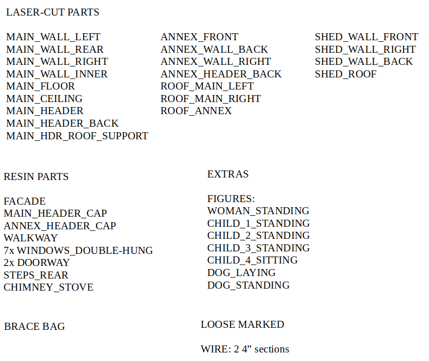
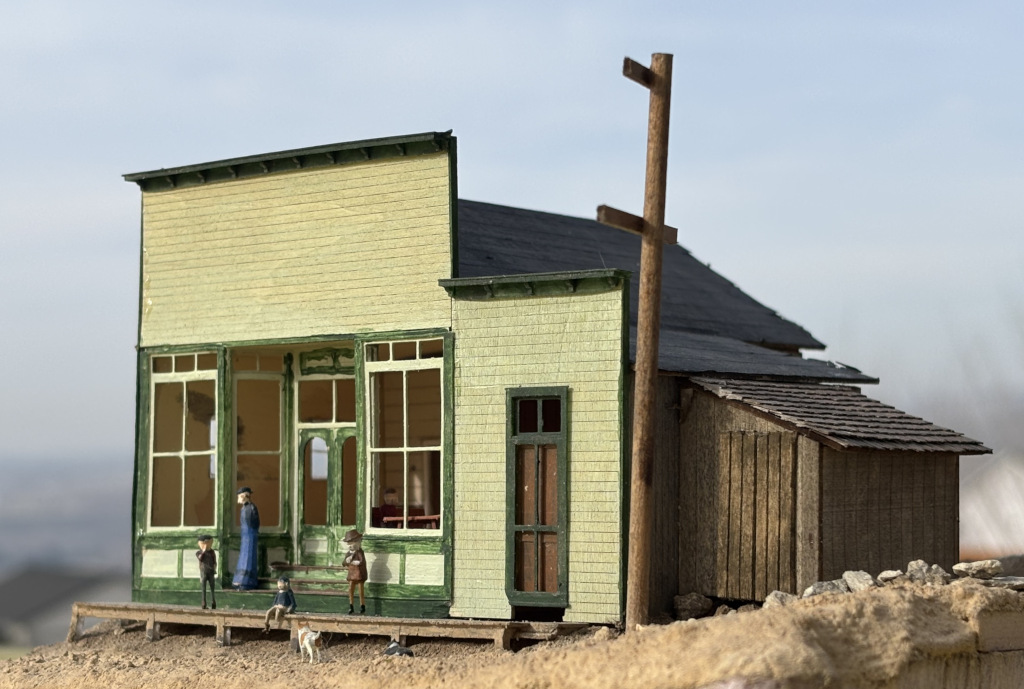
The figures shown also come with the kit. There is some evidence that the woman with her children as well as the two men down the street at the hotel are waiting for the stage to ??? – possibly Emmett being the closest town and it had the railroad. Direct to Boise by stage may have been quicker though.
Lumber Pieces
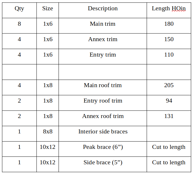
Suggested Stripwood Cut Guide
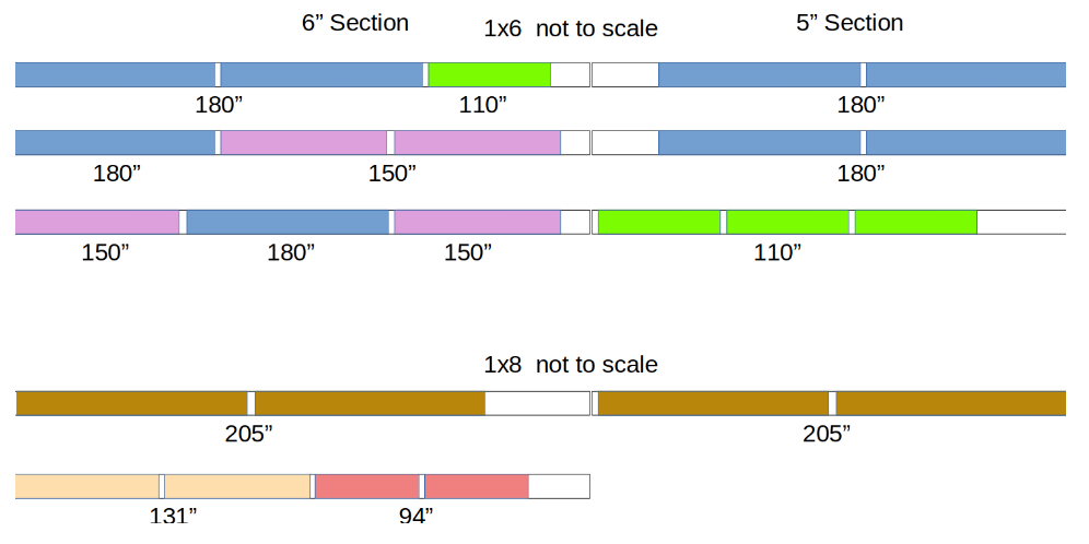
These sections are approximately to scale but not close enough to use to cut templates.
Measure to the model pieces and cut to fit