Miner’s Cabin
Out along the old 1840s Emigrant Trail along the Truckee River Route – just west of the Humboldt Sink – was the most difficult terrain of the journey. Hot, dry, and sandy, covered with vast alkali flats, there was no water between the Humboldt Sink and the Truckee River some 40 miles distant. That could be almost a week-long journey … about ½-hour these days on I-80 which basically follows the route through Reno.
A rough wagon road was constructed by the late 1840s but travel was so difficult that by 1850 most chose to tackle the equally dreaded but easier travel of the Carson River Route through the 40-Mile Desert between the Humboldt Sink and the Carson Sink to follow the Carson River to the Sierra and over to Placerville more or less along what is now US50.
But there was silver and salt in the area, both valuable commodities, salt being used in silver processing. The Central Pacific built through here in 1868 along what is now I-80 (and the old railbed may be still seen in the median strip). The Desert Queen Mine was nearby. A significant gold deposit was discovered in 1908, causing the new mining boom town of Jessup to be established. For a short while, Jessup was home to around 300 people with saloons and grocery stores serving those that worked the 8 mines in the area. The boom was short-lived and by 1909, the mines had played out and by 1912, Jessup had faded away.
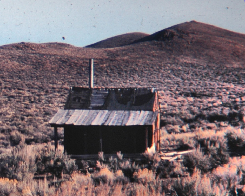
That area is still rough to travel – lack of traffic probably kept this little cabin out there in the hills intact. It is so typical of miner’s cabins of the era – and (maybe) still standing (complete with blue-enameled pots still hanging on the walls) that it is used as the basis for the Payette Valley Models “Miner’s Cabin” .
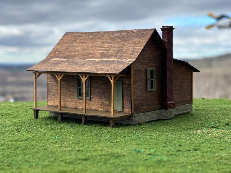
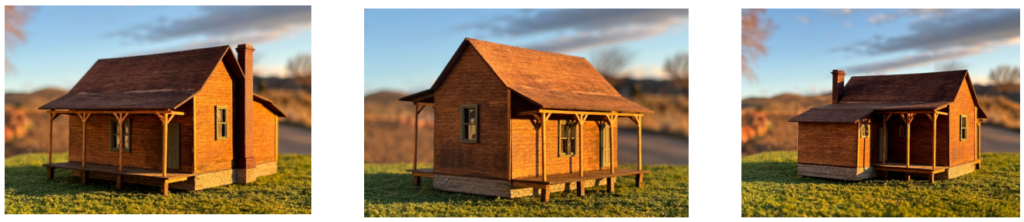
This model prototype was stained rather than painted. There would never have been paint applied to such a structure and oil stains work well. Another technique useful for keeping the bare aged wood look uses alcohol/chalk washes: Rembrandt Pastel Chalks being one possible choice. These come in a large variety of colors; alcohol washes using combinations of raw and burnt siennas and umbers being good choices for wood.
The foundation, doors, windows, and chimney are 3D-printed resin. Acrylic paints work well on these; oil stains and chalks not so much. The resin material likes a thin primer coat.
The foundation represents a field stone construction; a wash of concrete/grey colors works well.
Although the Jessup building has a tin stove pipe, there was evidence of a brick chimney at some time. We chose to go with a chimney. One method for coloring the chimney is to paint the chimney pumpkin orange as a base coat, then apply uneven washes of “brick color” acrylics to obtain the desired brick coloring.
Construction is straight-forward but assembly of the porch roof supports requires care and patience.
Construction
It is suggested the resin parts be painted before assembly. The foundation is of “field rock” and should be colored to represent the rocks of the region modelled. The doors and windows would be untreated wood and should be colored to represent the intended age of the model. Don’t forget the floor and edges – the floor edges are visible as sills on the model.
The wood walls are 1/16” thick – 5.44” in HO. The draft models were colored with Minwax oil-based stains. Other techniques can be used; a chalk/alcohol/ink wash works well. These structures were never painted; the specific color and treatment depends on the intended age of the model.
It is suggested that the walls of the main structure be painted or stained together. Bracing is suggested to be placed against the grain on the interior of the walls. Make sure the bracing does not interfere with assembly placement.
Walls
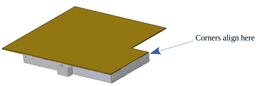
Begin construction by placing the floor onto the foundation. The back and sides line up with the foundation edges; the front extends over the foundation as a porch. The floor section has etching representing boards on a front and rear porch. These should be stained as such.
Place the windows and doors into the appropriate walls.
Fasten the rear wall to the right side wall. Titebond or similar wood construction glue is recommended; a white glue similar to Elmer’s is not appropriate. The rear wall butts onto the sidewall. Place a corner brace at the interior junction. Toothpicks are included to use as braces.
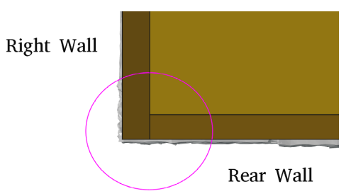
When the glue has set, place the walls on the floor such that the rear wall is lined up along the back edge of the floor. The right sidewall lines up along the right edge of the floor.
The left side annex wall (with door) is now placed to the rear wall and along the floor edge. This wall extends over the floor, leaving a section of floor as a rear porch.
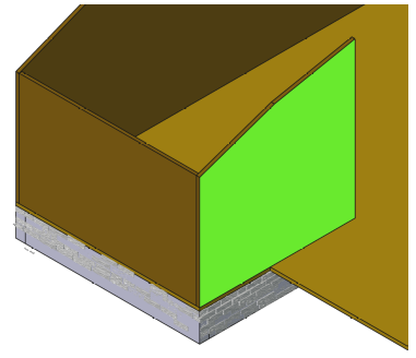
The main left wall is placed next. This wall is placed along the edge of the floor and butts into the front wall.
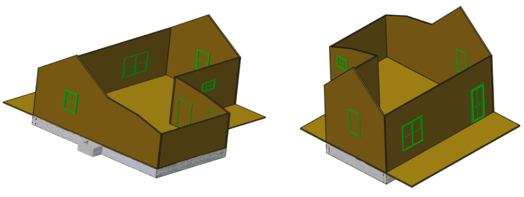
Finally place the main rear wall between the annex left wall and main left wall.
The model should now look similar to this:
Porches
Front
The porch supports are put together as a sub-assembly
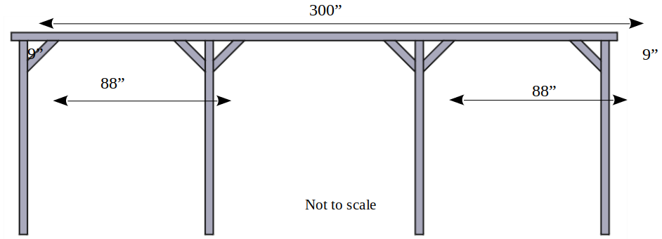
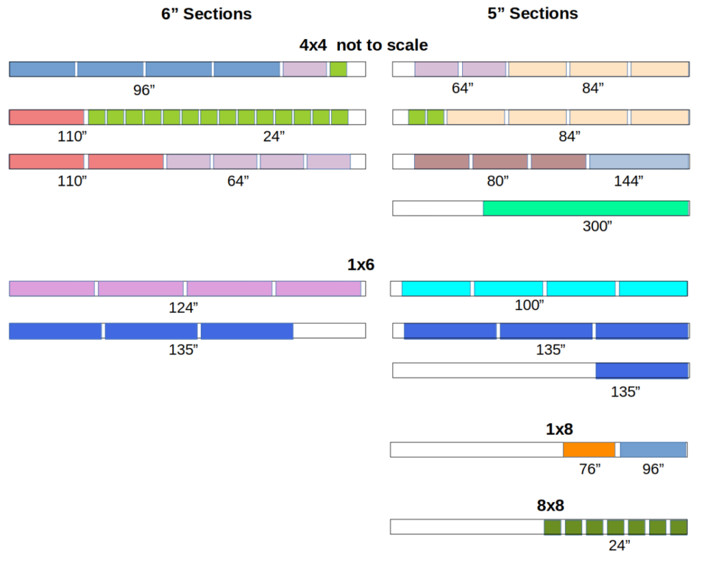
Cut a length of 4×4 to 300” as the cross beam (this length should be the same as the front porch section of the floor board). Cut four 96” lengths of 4×4 as roof support posts. Paint or stain the posts as desired before applying glue.
The two end posts are placed 9” from the ends with the two middle posts having an 88” gap from the end posts.
One method of attachment would be to place the beams on wax paper using square blocks to hold the cross beam in place. Put glue on the top of each post with a 90° square to assure a right angle. Let this assembly dry. Cut 17 22” lengths of 4×4. Cut each end to a 45° angle and place 6 pieces as shown. Let the glue set.
Set the assembly upright on the cross beam making sure it stands at a 90° angle. Cut four 64” lengths of 4×4 and place against the crossbeam as shown. Each piece should line up with the corresponding post.
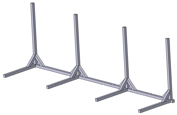
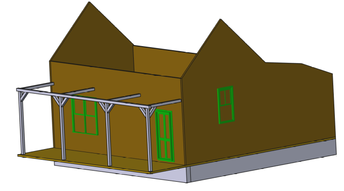
When the cross-posts are firmly attached, place four of the 45° support braces as shown. When the support assembly is dry, place against the front of the cabin as shown. The cross-beam should be the same width as the porch; the posts should be vertical.
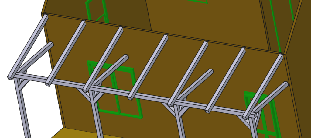
Cut seven 84” lengths of 4×4. One end may be beveled to 21° to fit flush against the front wall if desired. Four of these beams line up with the posts – each top edge flush with the top of the front wall, the other end lies across the cross-beam. The other three are placed midway between posts. The end result should appear as:
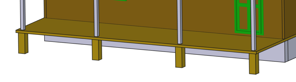
Cut seven 24” long sections of 8×8 (the height between “ground” and bottom of floor). Size the posts to the height of the foundation rather than cutting to exactly 24”.
Place 4 centered under the floor beneath each post. The other three are used on the back porch.
Rear Porch
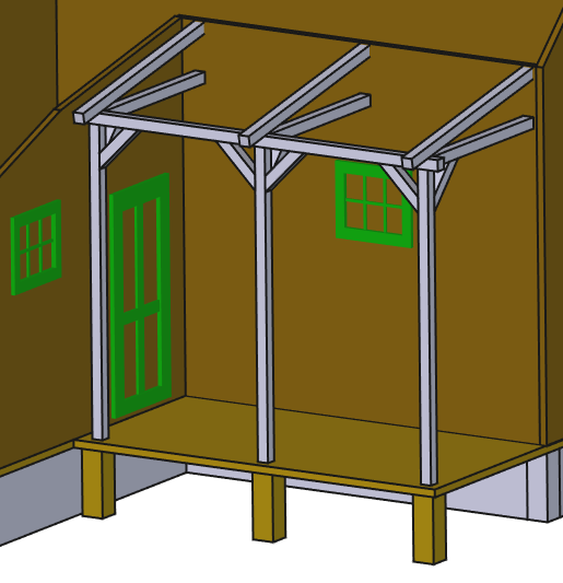
A similar procedure as with the front porch is used to construct the rear porch support. The cross-beam is 144” long (length of the back porch), the posts are 110” high, the beams are 64” long, the roof support beams are 80” long with an 11° bevel.
The outer posts sit 6” from each end of the cross-beam; there is 61” between the outer and middle posts. The remaining 45° braces are used as shown
Use the remaining three 24” long 8x8s under each post.
Trim
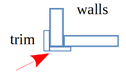
Stain or paint the trim before assembly. Cut four sections of 1×6 of about 114” length as trim along the roof line of the main structure. Trim doesn’t extend rear of the chimney on the right wall. The annex roof line does not have trim.
Cut other lengths of 1×6 to fit as corner trim. The trim pieces fit over the corners as shown below
Chimney
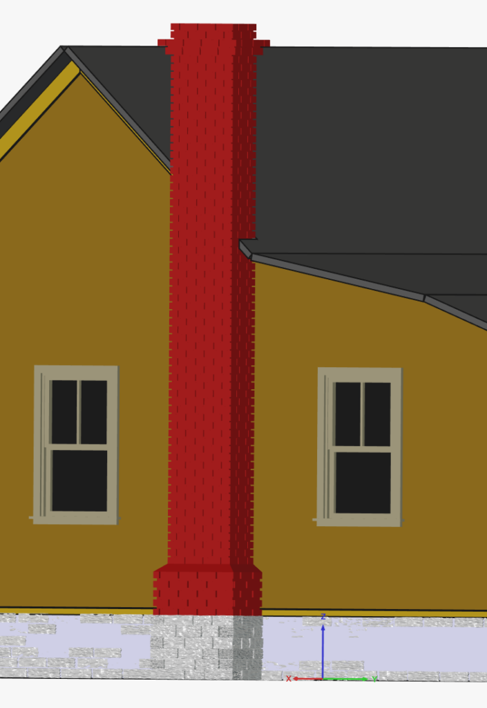
The chimney should be placed against the right wall and centered on the chimney base on the foundation. The chimney also fits a notch in the roof.
One method of coloring the chimney is to paint an initial coat of orange, then with thinned washes of red oxide and/or other “brick” colors. A black wash at the top might represent smoke stain. Leave the chimney hanging upside down so that the black wash drips towards the chimney top.
Roof
Place the roof pieces to the model starting with the two main halves. Place so that the overhang on each side is equal and that the rear half fits tightly against the chimney. Once fastened, place the other sections: the front pooch, the rear porch, and finally the rear room.
The kit does not include roofing material. Wooden shake shingles of different styles and colors are available from several manufacturers – Wild West Scale Models offers a nice selection as do others.
A tarpaper roof would not be inappropriate: 3 foot wide strips of paper towel can work well. Aleens Tacky Glue is useful for fastening paper to the roof sections. A 50:50 dilute wash of Elmer’s Glue may also be used. After dry, a black-gray wash is used for coloring. Thin strips of lumber – 1×2 or 1×3 – can be placed every 6 or 8 feet to run up the roof sections, acting as hold-downs of the tarpaper.
A later version of the cabin might also have corrugated tin roofing – perhaps placed over worn-out shake shingles.
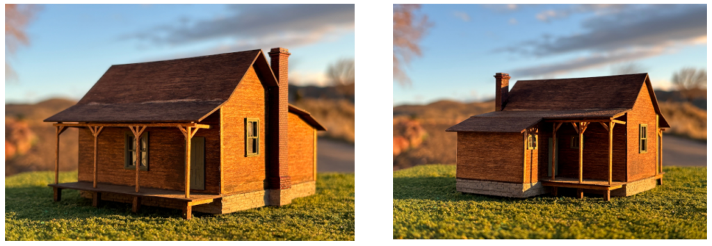
This completes the Miner’s Cabin model.
Lumber Pieces
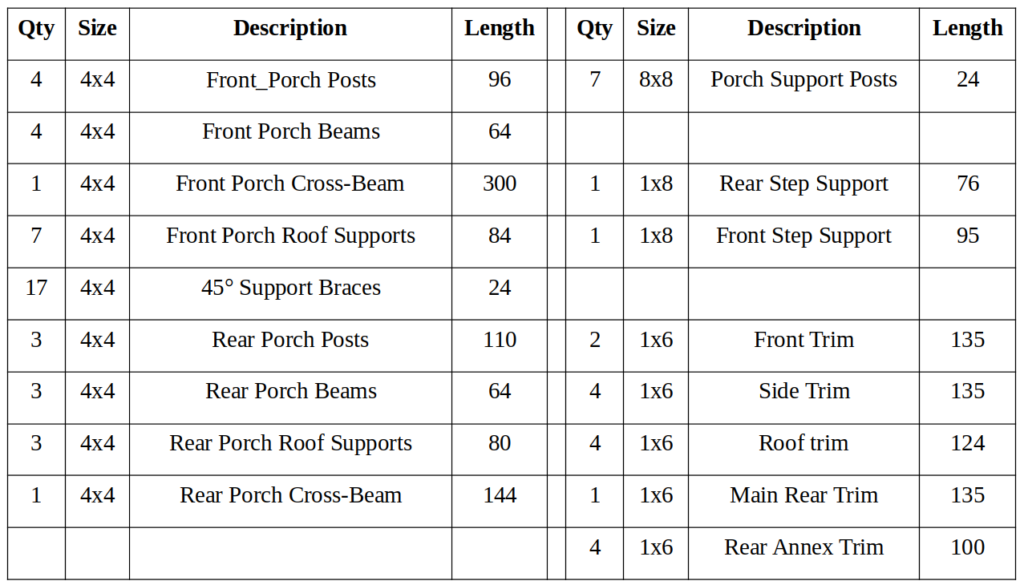
Grouped pieces should be cut together, especially the 45° brace pieces. Trim pieces should be cut to fit. The 8×8 porch support posts should come to the top of the foundation.
Suggested Lumber Cut Diagram
The illustrations are roughly to scale but should be measured against the actual pieces.